VOTING POWER100.00%
DOWNVOTE POWER100.00%
RESOURCE CREDITS100.00%
REPUTATION PROGRESS0.00%
Net Worth
0.000USD
STEEM
0.001STEEM
SBD
0.000SBD
Effective Power
3.366SP
├── Own SP
0.000SP
└── Incoming DelegationsDeleg
+3.366SP
Detailed Balance
| STEEM | ||
| balance | 0.001STEEM | STEEM |
| market_balance | 0.000STEEM | STEEM |
| savings_balance | 0.000STEEM | STEEM |
| reward_steem_balance | 0.000STEEM | STEEM |
| STEEM POWER | ||
| Own SP | 0.000SP | SP |
| Delegated Out | 0.000SP | SP |
| Delegation In | 3.366SP | SP |
| Effective Power | 3.366SP | SP |
| Reward SP (pending) | 0.000SP | SP |
| SBD | ||
| sbd_balance | 0.000SBD | SBD |
| sbd_conversions | 0.000SBD | SBD |
| sbd_market_balance | 0.000SBD | SBD |
| savings_sbd_balance | 0.000SBD | SBD |
| reward_sbd_balance | 0.000SBD | SBD |
{
  "balance": "0.001 STEEM",
  "savings_balance": "0.000 STEEM",
  "reward_steem_balance": "0.000 STEEM",
  "vesting_shares": "0.000000 VESTS",
  "delegated_vesting_shares": "0.000000 VESTS",
  "received_vesting_shares": "5472.996220 VESTS",
  "sbd_balance": "0.000 SBD",
  "savings_sbd_balance": "0.000 SBD",
  "reward_sbd_balance": "0.000 SBD",
  "conversions": []
}
Account Info
| name | ceceliaanne |
| id | 1618387 |
| rank | 1,301,863 |
| reputation | 305934304 |
| created | 2021-10-25T07:43:24 |
| recovery_account | steem |
| proxy | None |
| post_count | 22 |
| comment_count | 0 |
| lifetime_vote_count | 0 |
| witnesses_voted_for | 0 |
| last_post | 2022-04-19T06:31:21 |
| last_root_post | 2022-04-19T06:31:21 |
| last_vote_time | 1970-01-01T00:00:00 |
| proxied_vsf_votes | 0, 0, 0, 0 |
| can_vote | 1 |
| voting_power | 0 |
| delayed_votes | 0 |
| balance | 0.001 STEEM |
| savings_balance | 0.000 STEEM |
| sbd_balance | 0.000 SBD |
| savings_sbd_balance | 0.000 SBD |
| vesting_shares | 0.000000 VESTS |
| delegated_vesting_shares | 0.000000 VESTS |
| received_vesting_shares | 5472.996220 VESTS |
| reward_vesting_balance | 0.000000 VESTS |
| vesting_balance | 0.000 STEEM |
| vesting_withdraw_rate | 0.000000 VESTS |
| next_vesting_withdrawal | 1969-12-31T23:59:59 |
| withdrawn | 0 |
| to_withdraw | 0 |
| withdraw_routes | 0 |
| savings_withdraw_requests | 0 |
| last_account_recovery | 1970-01-01T00:00:00 |
| reset_account | null |
| last_owner_update | 1970-01-01T00:00:00 |
| last_account_update | 1970-01-01T00:00:00 |
| mined | No |
| sbd_seconds | 0 |
| sbd_last_interest_payment | 1970-01-01T00:00:00 |
| savings_sbd_last_interest_payment | 1970-01-01T00:00:00 |
{
  "active": {
    "account_auths": [],
    "key_auths": [
      [
        "STM7uCgFyXos3s3VNYmPyQjrCqdPGdSL83Zc18GT4D6RjgtEsXEKF",
        1
      ]
    ],
    "weight_threshold": 1
  },
  "balance": "0.001 STEEM",
  "can_vote": true,
  "comment_count": 0,
  "created": "2021-10-25T07:43:24",
  "curation_rewards": 0,
  "delegated_vesting_shares": "0.000000 VESTS",
  "downvote_manabar": {
    "current_mana": 1368249055,
    "last_update_time": 1769138346
  },
  "guest_bloggers": [],
  "id": 1618387,
  "json_metadata": "{}",
  "last_account_recovery": "1970-01-01T00:00:00",
  "last_account_update": "1970-01-01T00:00:00",
  "last_owner_update": "1970-01-01T00:00:00",
  "last_post": "2022-04-19T06:31:21",
  "last_root_post": "2022-04-19T06:31:21",
  "last_vote_time": "1970-01-01T00:00:00",
  "lifetime_vote_count": 0,
  "market_history": [],
  "memo_key": "STM6F2Uuq9fYDVqPWXpyyt5GP2V1c7DG9Z6ZRYf36Qc5CvBjQSGZ1",
  "mined": false,
  "name": "ceceliaanne",
  "next_vesting_withdrawal": "1969-12-31T23:59:59",
  "other_history": [],
  "owner": {
    "account_auths": [],
    "key_auths": [
      [
        "STM4xwoKsX6uj8ZBv7TnTrrtLNGhaV66jXQXXfFQaAjSHSYventHy",
        1
      ]
    ],
    "weight_threshold": 1
  },
  "pending_claimed_accounts": 0,
  "post_bandwidth": 0,
  "post_count": 22,
  "post_history": [],
  "posting": {
    "account_auths": [],
    "key_auths": [
      [
        "STM6rFK7LXh4E83n3ineUAhhmRVweizTcPKCsquzr2EyZmeyTrfWG",
        1
      ]
    ],
    "weight_threshold": 1
  },
  "posting_json_metadata": "",
  "posting_rewards": 0,
  "proxied_vsf_votes": [
    0,
    0,
    0,
    0
  ],
  "proxy": "",
  "received_vesting_shares": "5472.996220 VESTS",
  "recovery_account": "steem",
  "reputation": 305934304,
  "reset_account": "null",
  "reward_sbd_balance": "0.000 SBD",
  "reward_steem_balance": "0.000 STEEM",
  "reward_vesting_balance": "0.000000 VESTS",
  "reward_vesting_steem": "0.000 STEEM",
  "savings_balance": "0.000 STEEM",
  "savings_sbd_balance": "0.000 SBD",
  "savings_sbd_last_interest_payment": "1970-01-01T00:00:00",
  "savings_sbd_seconds": "0",
  "savings_sbd_seconds_last_update": "1970-01-01T00:00:00",
  "savings_withdraw_requests": 0,
  "sbd_balance": "0.000 SBD",
  "sbd_last_interest_payment": "1970-01-01T00:00:00",
  "sbd_seconds": "0",
  "sbd_seconds_last_update": "1970-01-01T00:00:00",
  "tags_usage": [],
  "to_withdraw": 0,
  "transfer_history": [],
  "vesting_balance": "0.000 STEEM",
  "vesting_shares": "0.000000 VESTS",
  "vesting_withdraw_rate": "0.000000 VESTS",
  "vote_history": [],
  "voting_manabar": {
    "current_mana": "5472996220",
    "last_update_time": 1769138346
  },
  "voting_power": 0,
  "withdraw_routes": 0,
  "withdrawn": 0,
  "witness_votes": [],
  "witnesses_voted_for": 0,
  "rank": 1301863
}
Withdraw Routes
| Incoming | Outgoing |
|---|---|
Empty | Empty |
{
  "incoming": [],
  "outgoing": []
}From Date
To Date
steemdelegated 3.366 SP to @ceceliaanne2026/01/23 03:19:06
steemdelegated 3.366 SP to @ceceliaanne
2026/01/23 03:19:06
| delegatee | ceceliaanne |
| delegator | steem |
| vesting shares | 5472.996220 VESTS |
| Transaction Info | Block #102846445/Trx 9e5c60a2b0c6a7dcd81e3cd7880a52fe59da21fe |
View Raw JSON Data
{
  "block": 102846445,
  "op": [
    "delegate_vesting_shares",
    {
      "delegatee": "ceceliaanne",
      "delegator": "steem",
      "vesting_shares": "5472.996220 VESTS"
    }
  ],
  "op_in_trx": 0,
  "timestamp": "2026-01-23T03:19:06",
  "trx_id": "9e5c60a2b0c6a7dcd81e3cd7880a52fe59da21fe",
  "trx_in_block": 5,
  "virtual_op": 0
}steemdelegated 3.467 SP to @ceceliaanne2024/12/16 22:38:21
steemdelegated 3.467 SP to @ceceliaanne
2024/12/16 22:38:21
| delegatee | ceceliaanne |
| delegator | steem |
| vesting shares | 5637.215417 VESTS |
| Transaction Info | Block #91292849/Trx a10e3a92fcd642c5b9d0f9a63ba1a4e3e8b440ef |
View Raw JSON Data
{
  "block": 91292849,
  "op": [
    "delegate_vesting_shares",
    {
      "delegatee": "ceceliaanne",
      "delegator": "steem",
      "vesting_shares": "5637.215417 VESTS"
    }
  ],
  "op_in_trx": 0,
  "timestamp": "2024-12-16T22:38:21",
  "trx_id": "a10e3a92fcd642c5b9d0f9a63ba1a4e3e8b440ef",
  "trx_in_block": 5,
  "virtual_op": 0
}steemdelegated 3.571 SP to @ceceliaanne2023/11/13 14:23:24
steemdelegated 3.571 SP to @ceceliaanne
2023/11/13 14:23:24
| delegatee | ceceliaanne |
| delegator | steem |
| vesting shares | 5806.348949 VESTS |
| Transaction Info | Block #79847112/Trx 127ad5a57aaefea82e93e90e42534912bb0536df |
View Raw JSON Data
{
  "block": 79847112,
  "op": [
    "delegate_vesting_shares",
    {
      "delegatee": "ceceliaanne",
      "delegator": "steem",
      "vesting_shares": "5806.348949 VESTS"
    }
  ],
  "op_in_trx": 0,
  "timestamp": "2023-11-13T14:23:24",
  "trx_id": "127ad5a57aaefea82e93e90e42534912bb0536df",
  "trx_in_block": 2,
  "virtual_op": 0
}steemdelegated 5.378 SP to @ceceliaanne2023/09/21 19:51:12
steemdelegated 5.378 SP to @ceceliaanne
2023/09/21 19:51:12
| delegatee | ceceliaanne |
| delegator | steem |
| vesting shares | 8743.627735 VESTS |
| Transaction Info | Block #78345470/Trx 662621238a49143d61197a5344a81828f3a6e50a |
View Raw JSON Data
{
  "block": 78345470,
  "op": [
    "delegate_vesting_shares",
    {
      "delegatee": "ceceliaanne",
      "delegator": "steem",
      "vesting_shares": "8743.627735 VESTS"
    }
  ],
  "op_in_trx": 0,
  "timestamp": "2023-09-21T19:51:12",
  "trx_id": "662621238a49143d61197a5344a81828f3a6e50a",
  "trx_in_block": 0,
  "virtual_op": 0
}steemdelegated 5.515 SP to @ceceliaanne2022/11/03 09:52:18
steemdelegated 5.515 SP to @ceceliaanne
2022/11/03 09:52:18
| delegatee | ceceliaanne |
| delegator | steem |
| vesting shares | 8965.309173 VESTS |
| Transaction Info | Block #69111073/Trx 6e71177b068babf06c4448c315403c2ab6ebf971 |
View Raw JSON Data
{
  "block": 69111073,
  "op": [
    "delegate_vesting_shares",
    {
      "delegatee": "ceceliaanne",
      "delegator": "steem",
      "vesting_shares": "8965.309173 VESTS"
    }
  ],
  "op_in_trx": 0,
  "timestamp": "2022-11-03T09:52:18",
  "trx_id": "6e71177b068babf06c4448c315403c2ab6ebf971",
  "trx_in_block": 0,
  "virtual_op": 0
}steemdelegated 16.738 SP to @ceceliaanne2022/06/15 22:40:06
steemdelegated 16.738 SP to @ceceliaanne
2022/06/15 22:40:06
| delegatee | ceceliaanne |
| delegator | steem |
| vesting shares | 27211.391191 VESTS |
| Transaction Info | Block #65091233/Trx 11caa464e3bcbf63a2012207feba0244c35021ef |
View Raw JSON Data
{
  "block": 65091233,
  "op": [
    "delegate_vesting_shares",
    {
      "delegatee": "ceceliaanne",
      "delegator": "steem",
      "vesting_shares": "27211.391191 VESTS"
    }
  ],
  "op_in_trx": 0,
  "timestamp": "2022-06-15T22:40:06",
  "trx_id": "11caa464e3bcbf63a2012207feba0244c35021ef",
  "trx_in_block": 4,
  "virtual_op": 0
}ceceliaannepublished a new post: new-era-of-new-photoelectric-sensor-technology2022/04/19 06:31:21
ceceliaannepublished a new post: new-era-of-new-photoelectric-sensor-technology
2022/04/19 06:31:21
| author | ceceliaanne |
| body | There have been new developments in the development direction and application field of photoelectric sensors, and on different occasions, photoelectric sensors will follow the differences in technology to develop the technology to a certain level. Then the technology of the photoelectric sensor can be understood as: Photoelectric sensors are sensors that use photoelectric elements as detection elements. It first converts the measured changes into changes in optical signals, and then further converts the optical signals into electrical signals with the help of photoelectric elements. The photoelectric sensor produces a photoelectric effect after being irradiated by visible light and converts the light signal into an electrical signal for output. In addition to measuring light intensity, it can also measure a variety of physical quantities, such as size, displacement, speed, temperature, etc., by using light transmission, occlusion, reflection, interference, etc., so it is an important sensitive device photoelectric sensor with a wide range of applications It is generally composed of three parts: light source, optical path, and optoelectronic components. The photoelectric detection method has the advantages of high precision, fast response, non-contact, etc., and can measure many parameters. The structure of the sensor is simple and the form is flexible and diverse. Therefore, the photoelectric sensor is widely used in detection and control. Exceptionally, the photoelectric effect of a photoelectric sensor is mainly a physical phenomenon in which light is irradiated on certain substances and the electrical properties of the substances are changed, which can be divided into two categories: external photoelectric effect and the 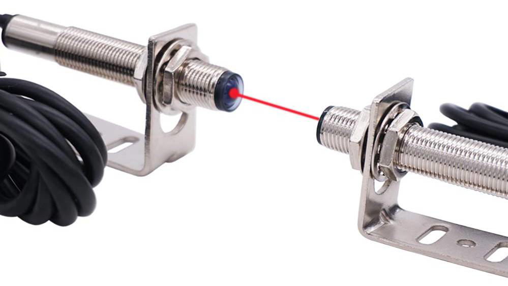 internal photoelectric effect. The external photoelectric effect refers to the physical phenomenon in which electrons in an object escape from the surface of the object and are emitted outward under the action of light. Photons are descriptions of electromagnetic waves in the visible light band in the form of quantized "particles". Photons have energy hv, where h is Planck's constant and v is the frequency of light. The photon flux corresponds to the light intensity. Learn more: https://www.easybom.com/blog/a/photoelectric-sensor-an-electronic-guide-to-it |
| json metadata | {"tags":["electronics","sensor"],"image":["https://cdn.steemitimages.com/DQmU538sjxWghJQdeDdehQyufmqxuAVHgmMHSX1CYbARrXT/4.18%206.jpg"],"links":["https://www.easybom.com/blog/a/photoelectric-sensor-an-electronic-guide-to-it"],"app":"steemit/0.2","format":"markdown"} |
| parent author | |
| parent permlink | electronics |
| permlink | new-era-of-new-photoelectric-sensor-technology |
| title | New era of new photoelectric sensor technology |
| Transaction Info | Block #63437004/Trx 29ebcced8ecec25c2a219e1308f3d00096e1ef42 |
View Raw JSON Data
{
"block": 63437004,
"op": [
"comment",
{
"author": "ceceliaanne",
"body": "There have been new developments in the development direction and application field of photoelectric sensors, and on different occasions, photoelectric sensors will follow the differences in technology to develop the technology to a certain level. Then the technology of the photoelectric sensor can be understood as:\nPhotoelectric sensors are sensors that use photoelectric elements as detection elements. It first converts the measured changes into changes in optical signals, and then further converts the optical signals into electrical signals with the help of photoelectric elements. The photoelectric sensor produces a photoelectric effect after being irradiated by visible light and converts the light signal into an electrical signal for output. In addition to measuring light intensity, it can also measure a variety of physical quantities, such as size, displacement, speed, temperature, etc., by using light transmission, occlusion, reflection, interference, etc., so it is an important sensitive device photoelectric sensor with a wide range of applications It is generally composed of three parts: light source, optical path, and optoelectronic components. The photoelectric detection method has the advantages of high precision, fast response, non-contact, etc., and can measure many parameters. The structure of the sensor is simple and the form is flexible and diverse. Therefore, the photoelectric sensor is widely used in detection and control.\nExceptionally, the photoelectric effect of a photoelectric sensor is mainly a physical phenomenon in which light is irradiated on certain substances and the electrical properties of the substances are changed, which can be divided into two categories: external photoelectric effect and the \n\ninternal photoelectric effect. The external photoelectric effect refers to the physical phenomenon in which electrons in an object escape from the surface of the object and are emitted outward under the action of light. Photons are descriptions of electromagnetic waves in the visible light band in the form of quantized \"particles\". Photons have energy hv, where h is Planck's constant and v is the frequency of light. The photon flux corresponds to the light intensity.\n\nLearn more: https://www.easybom.com/blog/a/photoelectric-sensor-an-electronic-guide-to-it",
"json_metadata": "{\"tags\":[\"electronics\",\"sensor\"],\"image\":[\"https://cdn.steemitimages.com/DQmU538sjxWghJQdeDdehQyufmqxuAVHgmMHSX1CYbARrXT/4.18%206.jpg\"],\"links\":[\"https://www.easybom.com/blog/a/photoelectric-sensor-an-electronic-guide-to-it\"],\"app\":\"steemit/0.2\",\"format\":\"markdown\"}",
"parent_author": "",
"parent_permlink": "electronics",
"permlink": "new-era-of-new-photoelectric-sensor-technology",
"title": "New era of new photoelectric sensor technology"
}
],
"op_in_trx": 0,
"timestamp": "2022-04-19T06:31:21",
"trx_id": "29ebcced8ecec25c2a219e1308f3d00096e1ef42",
"trx_in_block": 7,
"virtual_op": 0
}2022/04/06 08:58:54
2022/04/06 08:58:54
| author | ceceliaanne |
| body | @@ -1,8 +1,114 @@ +!%5B4.2 14.jpg%5D(https://cdn.steemitimages.com/DQmPWrduaymVfw2uMhHX6UxhubdHsGkT5T5p7XcU7mbMWGC/4.2%252014.jpg)%0A Non-cont |
| json metadata | {"tags":["sensor"],"links":["https://www.easybom.com/blog/a/capacitive-sensor-a-full-understanding-of-it"],"app":"steemit/0.2","format":"markdown","image":["https://cdn.steemitimages.com/DQmPWrduaymVfw2uMhHX6UxhubdHsGkT5T5p7XcU7mbMWGC/4.2%2014.jpg"]} |
| parent author | |
| parent permlink | electronics |
| permlink | difference-analysis-between-capacitive-sensor-and-eddy-current-sensor-detection-technology |
| title | Difference analysis between capacitive sensor and eddy current sensor detection technology |
| Transaction Info | Block #63068724/Trx 520418b7edb55927e01d361f8fea5369a15a1182 |
View Raw JSON Data
{
  "block": 63068724,
  "op": [
    "comment",
    {
      "author": "ceceliaanne",
      "body": "@@ -1,8 +1,114 @@\n+!%5B4.2 14.jpg%5D(https://cdn.steemitimages.com/DQmPWrduaymVfw2uMhHX6UxhubdHsGkT5T5p7XcU7mbMWGC/4.2%252014.jpg)%0A\n Non-cont\n",
      "json_metadata": "{\"tags\":[\"sensor\"],\"links\":[\"https://www.easybom.com/blog/a/capacitive-sensor-a-full-understanding-of-it\"],\"app\":\"steemit/0.2\",\"format\":\"markdown\",\"image\":[\"https://cdn.steemitimages.com/DQmPWrduaymVfw2uMhHX6UxhubdHsGkT5T5p7XcU7mbMWGC/4.2%2014.jpg\"]}",
      "parent_author": "",
      "parent_permlink": "electronics",
      "permlink": "difference-analysis-between-capacitive-sensor-and-eddy-current-sensor-detection-technology",
      "title": "Difference analysis between capacitive sensor and eddy current sensor detection technology"
    }
  ],
  "op_in_trx": 0,
  "timestamp": "2022-04-06T08:58:54",
  "trx_id": "520418b7edb55927e01d361f8fea5369a15a1182",
  "trx_in_block": 0,
  "virtual_op": 0
}2022/04/06 08:58:21
2022/04/06 08:58:21
| author | ceceliaanne |
| body | Non-contact sensors using capacitive and eddy current technologies each represent a unique combination of advantages and disadvantages in a variety of applications. Comparing the advantages of the two technologies will help you choose the best technology for your application. The following explains the difference in the performance structure of the different detection technologies between these two sensors: 1. The structure of the sensor The first thing to understand is the difference between capacitive and eddy current sensors, we must first look at their construction. The center of a capacitive probe is the detection element. This piece of stainless steel generates an electric field, which is used to detect the distance to the target. The guard ring and detection element are separated by an insulating layer, and the guard ring is also made of stainless steel. A guard ring surrounds the detection element and focuses the electric field on the target. Some electronic components are connected to the detection element and guard ring. All of these internal components are surrounded by insulation and encapsulated in stainless steel housing. The housing is connected to the ground shield of the cable. The main functional part of the eddy current probe is the induction coil. This is the coil near the end of the probe. An alternating current is passed through the coil to generate an alternating magnetic field. This magnetic field is used to detect the distance to the target. The coils are sealed with plastic and epoxy and housed in stainless steel housing. Because the magnetic field of an eddy current sensor is not as easy to focus as a capacitive sensor. On the probe of the eddy-current sensor, an epoxy-coated coil protrudes from the steel housing to allow the entire induced magnetic field to engage with the target. 2. Sensor spot size, target size, and measurement range The sensing area of the non-contact sensor probe engages the target within a certain area. The size of this area is called the spot size. The target must be larger than the spot size, otherwise, special calibration is required. The spot size is always proportional to the probe diameter. For capacitive and eddy-current sensors, there is a significant difference in the ratio between probe diameter and spot size. These different spot sizes will result in different minimum target size requirements. Capacitive sensors use an electric field for detection. The electric field is focused on the probe by the guard ring, which results in a spot size 30% larger than the diameter of the detection element. A typical ratio of detection range to detection element diameter is 1:8. This means that the diameter of the sensing element must be eight times larger for each range unit. For example, a 500µm detection range requires a 4000µm (4mm) detection element diameter. This ratio is used for typical calibrations. Calibration of high resolution and extended range will change this ratio. Eddy current sensors use a magnetic field that completely surrounds the tip of the probe. This produces a larger induction field, resulting in a spot size approximately three times the diameter of the probe's induction coil. For eddy current sensors, the ratio of detection range to induction coil diameter is 1:3. This means that for each range unit, the coil diameter must be three times larger. In this case, only one eddy current sensor probe with a diameter of 1500µm (1.5mm) is required for the same detection range of 500µm. When choosing an inspection technique, consider the target size. Smaller targets may require capacitive sensors. If the target size must be smaller than the sensor's spot size, special calibration may be able to compensate for inherent measurement errors. Learn more about the capacitive sensor. https://www.easybom.com/blog/a/capacitive-sensor-a-full-understanding-of-it |
| json metadata | {"tags":["electronics"],"links":["https://www.easybom.com/blog/a/capacitive-sensor-a-full-understanding-of-it"],"app":"steemit/0.2","format":"markdown"} |
| parent author | |
| parent permlink | electronics |
| permlink | difference-analysis-between-capacitive-sensor-and-eddy-current-sensor-detection-technology |
| title | Difference analysis between capacitive sensor and eddy current sensor detection technology |
| Transaction Info | Block #63068713/Trx 918ad550d735f08c88869312468e6436ca9c2df6 |
View Raw JSON Data
{
"block": 63068713,
"op": [
"comment",
{
"author": "ceceliaanne",
"body": "Non-contact sensors using capacitive and eddy current technologies each represent a unique combination of advantages and disadvantages in a variety of applications. Comparing the advantages of the two technologies will help you choose the best technology for your application. The following explains the difference in the performance structure of the different detection technologies between these two sensors:\n\n1. The structure of the sensor\n\nThe first thing to understand is the difference between capacitive and eddy current sensors, we must first look at their construction. The center of a capacitive probe is the detection element. This piece of stainless steel generates an electric field, which is used to detect the distance to the target. The guard ring and detection element are separated by an insulating layer, and the guard ring is also made of stainless steel. A guard ring surrounds the detection element and focuses the electric field on the target. Some electronic components are connected to the detection element and guard ring. All of these internal components are surrounded by insulation and encapsulated in stainless steel housing. The housing is connected to the ground shield of the cable.\n\nThe main functional part of the eddy current probe is the induction coil. This is the coil near the end of the probe. An alternating current is passed through the coil to generate an alternating magnetic field. This magnetic field is used to detect the distance to the target. The coils are sealed with plastic and epoxy and housed in stainless steel housing. Because the magnetic field of an eddy current sensor is not as easy to focus as a capacitive sensor. On the probe of the eddy-current sensor, an epoxy-coated coil protrudes from the steel housing to allow the entire induced magnetic field to engage with the target.\n\n2. Sensor spot size, target size, and measurement range\n\nThe sensing area of the non-contact sensor probe engages the target within a certain area. The size of this area is called the spot size. The target must be larger than the spot size, otherwise, special calibration is required. The spot size is always proportional to the probe diameter. For capacitive and eddy-current sensors, there is a significant difference in the ratio between probe diameter and spot size. These different spot sizes will result in different minimum target size requirements.\n\nCapacitive sensors use an electric field for detection. The electric field is focused on the probe by the guard ring, which results in a spot size 30% larger than the diameter of the detection element. A typical ratio of detection range to detection element diameter is 1:8. This means that the diameter of the sensing element must be eight times larger for each range unit. For example, a 500µm detection range requires a 4000µm (4mm) detection element diameter. This ratio is used for typical calibrations. Calibration of high resolution and extended range will change this ratio.\n\nEddy current sensors use a magnetic field that completely surrounds the tip of the probe. This produces a larger induction field, resulting in a spot size approximately three times the diameter of the probe's induction coil. For eddy current sensors, the ratio of detection range to induction coil diameter is 1:3. This means that for each range unit, the coil diameter must be three times larger. In this case, only one eddy current sensor probe with a diameter of 1500µm (1.5mm) is required for the same detection range of 500µm. When choosing an inspection technique, consider the target size. Smaller targets may require capacitive sensors. If the target size must be smaller than the sensor's spot size, special calibration may be able to compensate for inherent measurement errors.\n\nLearn more about the capacitive sensor. https://www.easybom.com/blog/a/capacitive-sensor-a-full-understanding-of-it",
"json_metadata": "{\"tags\":[\"electronics\"],\"links\":[\"https://www.easybom.com/blog/a/capacitive-sensor-a-full-understanding-of-it\"],\"app\":\"steemit/0.2\",\"format\":\"markdown\"}",
"parent_author": "",
"parent_permlink": "electronics",
"permlink": "difference-analysis-between-capacitive-sensor-and-eddy-current-sensor-detection-technology",
"title": "Difference analysis between capacitive sensor and eddy current sensor detection technology"
}
],
"op_in_trx": 0,
"timestamp": "2022-04-06T08:58:21",
"trx_id": "918ad550d735f08c88869312468e6436ca9c2df6",
"trx_in_block": 4,
"virtual_op": 0
}steemdelegated 16.849 SP to @ceceliaanne2022/03/27 15:06:18
steemdelegated 16.849 SP to @ceceliaanne
2022/03/27 15:06:18
| delegatee | ceceliaanne |
| delegator | steem |
| vesting shares | 27392.878365 VESTS |
| Transaction Info | Block #62789440/Trx 45b5dfcb4ef6d14126e97e6a0981d0a4b5485a7c |
View Raw JSON Data
{
  "block": 62789440,
  "op": [
    "delegate_vesting_shares",
    {
      "delegatee": "ceceliaanne",
      "delegator": "steem",
      "vesting_shares": "27392.878365 VESTS"
    }
  ],
  "op_in_trx": 0,
  "timestamp": "2022-03-27T15:06:18",
  "trx_id": "45b5dfcb4ef6d14126e97e6a0981d0a4b5485a7c",
  "trx_in_block": 10,
  "virtual_op": 0
}scitechreplied to @ceceliaanne / r8u1fz2022/03/16 10:07:12
scitechreplied to @ceceliaanne / r8u1fz
2022/03/16 10:07:12
| author | scitech |
| body | And silicon is an expensive commodity. |
| json metadata | {"app":"steemit/0.2"} |
| parent author | ceceliaanne |
| parent permlink | nano-solar-cells |
| permlink | r8u1fz |
| title | |
| Transaction Info | Block #62468243/Trx 8aef13de7533a4a9df72fe4a799c26b0bf5667c5 |
View Raw JSON Data
{
  "block": 62468243,
  "op": [
    "comment",
    {
      "author": "scitech",
      "body": "And silicon is an expensive commodity.",
      "json_metadata": "{\"app\":\"steemit/0.2\"}",
      "parent_author": "ceceliaanne",
      "parent_permlink": "nano-solar-cells",
      "permlink": "r8u1fz",
      "title": ""
    }
  ],
  "op_in_trx": 0,
  "timestamp": "2022-03-16T10:07:12",
  "trx_id": "8aef13de7533a4a9df72fe4a799c26b0bf5667c5",
  "trx_in_block": 5,
  "virtual_op": 0
}ceceliaannepublished a new post: nano-solar-cells2022/03/16 09:22:45
ceceliaannepublished a new post: nano-solar-cells
2022/03/16 09:22:45
| author | ceceliaanne |
| body | @@ -5879,20 +5879,16 @@ rmany.%0A%0A - Eric Old |
| json metadata | {"tags":["solar","cell"],"links":["https://www.easybom.com/blog/a/solar-cell-what-is-it-and-how-does-it-work"],"app":"steemit/0.2","format":"markdown"} |
| parent author | |
| parent permlink | electronics |
| permlink | nano-solar-cells |
| title | Nano solar cells |
| Transaction Info | Block #62467357/Trx b69ec6adc545d851c6d814275a5c01d2ac7ff4b3 |
View Raw JSON Data
{
  "block": 62467357,
  "op": [
    "comment",
    {
      "author": "ceceliaanne",
      "body": "@@ -5879,20 +5879,16 @@\n rmany.%0A%0A\n-    \n Eric Old\n",
      "json_metadata": "{\"tags\":[\"solar\",\"cell\"],\"links\":[\"https://www.easybom.com/blog/a/solar-cell-what-is-it-and-how-does-it-work\"],\"app\":\"steemit/0.2\",\"format\":\"markdown\"}",
      "parent_author": "",
      "parent_permlink": "electronics",
      "permlink": "nano-solar-cells",
      "title": "Nano solar cells"
    }
  ],
  "op_in_trx": 0,
  "timestamp": "2022-03-16T09:22:45",
  "trx_id": "b69ec6adc545d851c6d814275a5c01d2ac7ff4b3",
  "trx_in_block": 6,
  "virtual_op": 0
}ceceliaannepublished a new post: nano-solar-cells2022/03/16 09:22:09
ceceliaannepublished a new post: nano-solar-cells
2022/03/16 09:22:09
| author | ceceliaanne |
| body | Nano solar cells, imagine solar panels without plates. Just a thin layer of paint that converts sunlight into electricity. Keep dreaming: solar energy can be harvested on roofs and on window surfaces. Solar-powered buildings are no longer the preserve of Southern California, and places like China, India, Kenya, and others are starting to embrace solar power because now, it's cheaper than burning coal. This is the prospect that thin-film solar cells PowerSheet paint for us: solar energy is ubiquitous and affordable to the people of third world countries. The underlying technology has been around for decades, but this year, Silicon Valley company Nanosolar has developed the production technology that promises to become a reality. The company produces solar cells by a method similar to printing, spraying a layer of nano-coating that absorbs light energy onto metal only as thin as an aluminum foil so that the price of solar panels can be reduced to 1/10 of the current price. Founded at Google This year, Nanosolar's first commercial solar panel came out, funded by a $20 million grant from the U.S. Department of Energy and the U.S. Department of Energy. The cost has always been the biggest challenge in harnessing solar energy. Traditional solar cells require silicon as the material. And silicon is an expensive commodity. The current global silicon shortage is exacerbating the situation. In addition, conventional solar cells are backed by the glass, which is heavy and dangerous, and expensive to transport and install. This means that with the cheapest solar panels, it also costs $3 to produce 1 watt of electricity. To compete with coal, costs must shrink to $1/watt. Nanosolar cells use no silicon at all, work as efficiently as most commercial solar cells, and cost as little as 30 cents per watt. "Here we're talking about printing solar cells like a piece of cloth, printing it on a trailer, on a roof, anywhere you can imagine," said Dan Kamen, director of the UC Renewable Energy Laboratory. A remarkable initiative that has revolutionized the way we think about solar cells and the solar economy." In San Jose, California, Nanosolar has built what will soon be the world's first solar cell factory. When fully operational next year, the factory will produce 430 megawatts of electricity a year from cells, more than any other solar farm in the United States combined, chief executive Martin Rothison claims. The first 100,000 cells will be shipped to Europe for the construction of a 1.4 MW power station. At present, the biggest problem facing Nanololar is not whether its product functions live up to expectations, but how to meet the strong market demand. Take California as an example. The state recently launched the Million Solar Roof Program, which provides tax breaks and discounts for those who automatically use solar energy, and encourages the installation of 100,000 solar roofs each year for 10 years. A few days ago, Israel's Orion Solar Company and Bar-Ilan University have jointly developed a nano-dye solar cell. The key part of the cell is only 10 nanometers of titanium oxide. When sunlight hits the dye-coated titanium oxide particles, it absorbs light and transmits solar energy using organic dyes like natural photosynthesis, and passes through the titanium oxide. The conduction band converts solar energy into an electrical current. The company's head, Brian, said that this type of solar cell is characterized by high efficiency and low cost. Since the dye technology can also generate electricity in low light conditions in the morning and evening, they also used a new method invented by Professor Zaban, director of the Center for Advanced Materials and Nanotechnology at Bar-Ilan University, to link nano cells into large single solar cells. and Orion's dye cell technology, therefore, this solar cell has high photoelectric efficiency. In addition, for solar power generation to be successful, cost reduction is an important factor, not only the power generation cost is lower than the current fossil fuel power generation, but also the infrastructure cost is greatly reduced, otherwise consumers in many countries, especially developing countries, can only " Wang Yang sighed." Although the current silicon solar cell technology is relatively mature, the price has remained high. The power generation cost of this dye solar cell developed by them is only half of that of silicon solar cells, and the production line investment is only a small part of that of silicon solar cells. better market prospects. Bryan said that the product is expected to be commercialized next year. Their initial goal is not to compete with power companies, but to provide services to remote households in developing countries such as Asia, Africa, and Latin America that are not yet connected to electricity in developing countries that private power companies do not want. This is a huge market. He believes their dye-based solar cells, which can provide enough power for lighting and small appliances, will find use in these regions. According to the British "Guardian" report, another ultra-thin solar cell using nanotechnology that can be "printed" on aluminum foil has been continuously produced on the assembly line of a factory in California, USA. This solar cell is called by scientists the "revolution" of solar power generation. It was developed and produced by Nanosolar in Silicon Valley. Unlike the solar cells that more and more European consumers install on their roofs to generate electricity, the new battery can be "printed" on aluminum foil like a printed newspaper, with good elasticity and lightweight. Nanosolar expects the panels to generate electricity as cheaply as coal. Nanosolar said that orders for the product have been placed in mid-2009 and that a second plant will soon be put into operation in Germany. Eric Oldkop, NanoSolar's manager in Switzerland, said: "Our first solar panels will be used in a solar power plant in Germany. Our goal is to produce cells that generate electricity at a cost of 99 cents a watt. plate." The report said that in Europe, Japan, China, and the United States, several companies, like Nanosolar companies, are developing and producing different styles of "sheet" solar cells. The U.S. government and Silicon Valley entrepreneurs have invested $300 million in commercializing the technology. Learn more: https://www.easybom.com/blog/a/solar-cell-what-is-it-and-how-does-it-work |
| json metadata | {"tags":["electronics","solar","cell"],"links":["https://www.easybom.com/blog/a/solar-cell-what-is-it-and-how-does-it-work"],"app":"steemit/0.2","format":"markdown"} |
| parent author | |
| parent permlink | electronics |
| permlink | nano-solar-cells |
| title | Nano solar cells |
| Transaction Info | Block #62467345/Trx d4a366c779773a90b5895d126c96992754a8dc76 |
View Raw JSON Data
{
  "block": 62467345,
  "op": [
    "comment",
    {
      "author": "ceceliaanne",
      "body": "Nano solar cells, imagine solar panels without plates. Just a thin layer of paint that converts sunlight into electricity. Keep dreaming: solar energy can be harvested on roofs and on window surfaces. Solar-powered buildings are no longer the preserve of Southern California, and places like China, India, Kenya, and others are starting to embrace solar power because now, it's cheaper than burning coal. This is the prospect that thin-film solar cells PowerSheet paint for us: solar energy is ubiquitous and affordable to the people of third world countries. The underlying technology has been around for decades, but this year, Silicon Valley company Nanosolar has developed the production technology that promises to become a reality.\n\nThe company produces solar cells by a method similar to printing, spraying a layer of nano-coating that absorbs light energy onto metal only as thin as an aluminum foil so that the price of solar panels can be reduced to 1/10 of the current price. Founded at Google This year, Nanosolar's first commercial solar panel came out, funded by a $20 million grant from the U.S. Department of Energy and the U.S. Department of Energy.\n\nThe cost has always been the biggest challenge in harnessing solar energy. Traditional solar cells require silicon as the material. And silicon is an expensive commodity. The current global silicon shortage is exacerbating the situation. In addition, conventional solar cells are backed by the glass, which is heavy and dangerous, and expensive to transport and install. This means that with the cheapest solar panels, it also costs $3 to produce 1 watt of electricity. To compete with coal, costs must shrink to $1/watt.\n\nNanosolar cells use no silicon at all, work as efficiently as most commercial solar cells, and cost as little as 30 cents per watt. \"Here we're talking about printing solar cells like a piece of cloth, printing it on a trailer, on a roof, anywhere you can imagine,\" said Dan Kamen, director of the UC Renewable Energy Laboratory. A remarkable initiative that has revolutionized the way we think about solar cells and the solar economy.\"\n\nIn San Jose, California, Nanosolar has built what will soon be the world's first solar cell factory. When fully operational next year, the factory will produce 430 megawatts of electricity a year from cells, more than any other solar farm in the United States combined, chief executive Martin Rothison claims. The first 100,000 cells will be shipped to Europe for the construction of a 1.4 MW power station.\n\nAt present, the biggest problem facing Nanololar is not whether its product functions live up to expectations, but how to meet the strong market demand. Take California as an example. The state recently launched the Million Solar Roof Program, which provides tax breaks and discounts for those who automatically use solar energy, and encourages the installation of 100,000 solar roofs each year for 10 years.\n\nA few days ago, Israel's Orion Solar Company and Bar-Ilan University have jointly developed a nano-dye solar cell. The key part of the cell is only 10 nanometers of titanium oxide. When sunlight hits the dye-coated titanium oxide particles, it absorbs light and transmits solar energy using organic dyes like natural photosynthesis, and passes through the titanium oxide. The conduction band converts solar energy into an electrical current.\n\nThe company's head, Brian, said that this type of solar cell is characterized by high efficiency and low cost. Since the dye technology can also generate electricity in low light conditions in the morning and evening, they also used a new method invented by Professor Zaban, director of the Center for Advanced Materials and Nanotechnology at Bar-Ilan University, to link nano cells into large single solar cells. and Orion's dye cell technology, therefore, this solar cell has high photoelectric efficiency.\n\nIn addition, for solar power generation to be successful, cost reduction is an important factor, not only the power generation cost is lower than the current fossil fuel power generation, but also the infrastructure cost is greatly reduced, otherwise consumers in many countries, especially developing countries, can only \" Wang Yang sighed.\" Although the current silicon solar cell technology is relatively mature, the price has remained high. The power generation cost of this dye solar cell developed by them is only half of that of silicon solar cells, and the production line investment is only a small part of that of silicon solar cells. better market prospects.\n\nBryan said that the product is expected to be commercialized next year. Their initial goal is not to compete with power companies, but to provide services to remote households in developing countries such as Asia, Africa, and Latin America that are not yet connected to electricity in developing countries that private power companies do not want. This is a huge market. He believes their dye-based solar cells, which can provide enough power for lighting and small appliances, will find use in these regions.\n\nAccording to the British \"Guardian\" report, another ultra-thin solar cell using nanotechnology that can be \"printed\" on aluminum foil has been continuously produced on the assembly line of a factory in California, USA. This solar cell is called by scientists the \"revolution\" of solar power generation. It was developed and produced by Nanosolar in Silicon Valley. Unlike the solar cells that more and more European consumers install on their roofs to generate electricity, the new battery can be \"printed\" on aluminum foil like a printed newspaper, with good elasticity and lightweight. Nanosolar expects the panels to generate electricity as cheaply as coal.\n\nNanosolar said that orders for the product have been placed in mid-2009 and that a second plant will soon be put into operation in Germany.\n\n    Eric Oldkop, NanoSolar's manager in Switzerland, said: \"Our first solar panels will be used in a solar power plant in Germany. Our goal is to produce cells that generate electricity at a cost of 99 cents a watt. plate.\"     \n\nThe report said that in Europe, Japan, China, and the United States, several companies, like Nanosolar companies, are developing and producing different styles of \"sheet\" solar cells. The U.S. government and Silicon Valley entrepreneurs have invested $300 million in commercializing the technology.\n\nLearn more: https://www.easybom.com/blog/a/solar-cell-what-is-it-and-how-does-it-work",
      "json_metadata": "{\"tags\":[\"electronics\",\"solar\",\"cell\"],\"links\":[\"https://www.easybom.com/blog/a/solar-cell-what-is-it-and-how-does-it-work\"],\"app\":\"steemit/0.2\",\"format\":\"markdown\"}",
      "parent_author": "",
      "parent_permlink": "electronics",
      "permlink": "nano-solar-cells",
      "title": "Nano solar cells"
    }
  ],
  "op_in_trx": 0,
  "timestamp": "2022-03-16T09:22:09",
  "trx_id": "d4a366c779773a90b5895d126c96992754a8dc76",
  "trx_in_block": 0,
  "virtual_op": 0
}ceceliaannepublished a new post: thyristor-replacement-experience2022/03/03 09:43:54
ceceliaannepublished a new post: thyristor-replacement-experience
2022/03/03 09:43:54
| author | ceceliaanne |
| body | After the thyristor is damaged, if there is no thyristor of the same type to be replaced, it can be replaced by another type of thyristor with similar performance parameters. When designing the application circuit, a large margin is generally reserved. When replacing a thyristor, just pay attention to its rated peak voltage (repetitive peak voltage), rated current (on-state average current), gate trigger voltage, and gate trigger current, especially the rated peak voltage and rated current. The replacement thyristor should be consistent with the switching speed of the damaged thyristor. For example, after the high-speed thyristor used in the pulse circuit and the high-speed inverter circuit is damaged, only the same type of fast thyristor can be used instead of the ordinary thyristor. When choosing a replacement thyristor, no matter what the parameters are, there is no need to leave an excessive margin, and it should be as close as possible to the parameters of the replaced thyristor because the excessive margin is not only a waste but also sometimes has side effects. , there are phenomena such as no triggering or insensitive triggering. In addition, it should be noted that the shape of the two thyristors should be the same, otherwise it will bring disadvantages to the installation work. Learn more about thyristor. https://www.easybom.com/blog/a/the-best-electronics-tutorial-for-thyristor |
| json metadata | {"tags":["electronics"],"links":["https://www.easybom.com/blog/a/the-best-electronics-tutorial-for-thyristor"],"app":"steemit/0.2","format":"markdown"} |
| parent author | |
| parent permlink | electronics |
| permlink | thyristor-replacement-experience |
| title | Thyristor replacement experience |
| Transaction Info | Block #62095230/Trx a7d683e4e6c4745d28fffae04370b768bea21fd4 |
View Raw JSON Data
{
  "block": 62095230,
  "op": [
    "comment",
    {
      "author": "ceceliaanne",
      "body": "After the thyristor is damaged, if there is no thyristor of the same type to be replaced, it can be replaced by another type of thyristor with similar performance parameters.\nWhen designing the application circuit, a large margin is generally reserved. When replacing a thyristor, just pay attention to its rated peak voltage (repetitive peak voltage), rated current (on-state average current), gate trigger voltage, and gate trigger current, especially the rated peak voltage and rated current.\n\nThe replacement thyristor should be consistent with the switching speed of the damaged thyristor. For example, after the high-speed thyristor used in the pulse circuit and the high-speed inverter circuit is damaged, only the same type of fast thyristor can be used instead of the ordinary thyristor.\n\nWhen choosing a replacement thyristor, no matter what the parameters are, there is no need to leave an excessive margin, and it should be as close as possible to the parameters of the replaced thyristor because the excessive margin is not only a waste but also sometimes has side effects. , there are phenomena such as no triggering or insensitive triggering.\n\nIn addition, it should be noted that the shape of the two thyristors should be the same, otherwise it will bring disadvantages to the installation work.\n\nLearn more about thyristor.\nhttps://www.easybom.com/blog/a/the-best-electronics-tutorial-for-thyristor",
      "json_metadata": "{\"tags\":[\"electronics\"],\"links\":[\"https://www.easybom.com/blog/a/the-best-electronics-tutorial-for-thyristor\"],\"app\":\"steemit/0.2\",\"format\":\"markdown\"}",
      "parent_author": "",
      "parent_permlink": "electronics",
      "permlink": "thyristor-replacement-experience",
      "title": "Thyristor replacement experience"
    }
  ],
  "op_in_trx": 0,
  "timestamp": "2022-03-03T09:43:54",
  "trx_id": "a7d683e4e6c4745d28fffae04370b768bea21fd4",
  "trx_in_block": 3,
  "virtual_op": 0
}ceceliaannepublished a new post: what-does-the-temperature-sensor-do2022/02/28 08:57:00
ceceliaannepublished a new post: what-does-the-temperature-sensor-do
2022/02/28 08:57:00
| author | ceceliaanne |
| body | When the outer barrel is filled with water, since the connection between the outer barrel and the temperature is in a sealed state, the pressure in the air pipe gradually increases as the water level rises, and the pressure in the air pipe generates a thrust on the film in the switch through the temperature air nozzle. When the force reaches the set mark, the thimble connected to the film pushes the contact strip to deform, so that the contact is pulled in and the water level is controlled. That is, under the action of air pressure, the shrapnel contacts the computer board and sends a signal to enter the washing state. At this point, the temperature task is completed. If the water level drops during the washing process, the shrapnel is disconnected and sends a signal to the computer board to replenish water to the set water level. If the airtightness is not good, the pressure in the trachea will deviate from the actual requirements (small), resulting in a high actual water level. When the user selects the highest water level, the injected water will be too high. If the edge overflows, there will be more than water ingress failure; if the temperature shrapnel cannot be reset after being pushed up, it will cause a non-dehydration failure. The temperature is 24VDC power supply, one relay switch output is active (24VDC), the lower water level sensor detects that there is no water, the relay switch is closed, and the pump starts to pump water; until the upper water level sensor detects that there is water, the relay switch is disconnected, and the pump stops pumping water. The liquid level control switch can be equipped with three liquid level sensor probes: FS-IR02, FS-IR12, FS-IR32A, and FS-IR42. The biggest difference between these three sensors is the type of installation. The surface material of the liquid level sensor is made of PC and polysulfone, which is used for various liquid level measurements. Except for the following liquids, strong acid, strong alkali, and other corrosive liquids cannot be used; such as sulfuric acid, hydrochloric acid, nitric acid, KOH, NaOH, etc. The liquid level switch adopts advanced circuit design and program optimization, which can eliminate the influence of external factors such as scale, water vapor, and water droplets on the measurement accuracy and accuracy. Of course, you should also pay more attention to maintenance and cleaning. Learn more about the temperature sensor. https://www.easybom.com/blog/a/ds18b20-temperature-sensor-circuit-pinout-and-datasheet |
| json metadata | {"tags":["electronics","sensor"],"links":["https://www.easybom.com/blog/a/ds18b20-temperature-sensor-circuit-pinout-and-datasheet"],"app":"steemit/0.2","format":"markdown"} |
| parent author | |
| parent permlink | electronics |
| permlink | what-does-the-temperature-sensor-do |
| title | What does the temperature sensor do? |
| Transaction Info | Block #62008325/Trx 42d6e6b7aaaf265fb3c4b79ccfcdf00695cf50cd |
View Raw JSON Data
{
  "block": 62008325,
  "op": [
    "comment",
    {
      "author": "ceceliaanne",
      "body": "When the outer barrel is filled with water, since the connection between the outer barrel and the temperature is in a sealed state, the pressure in the air pipe gradually increases as the water level rises, and the pressure in the air pipe generates a thrust on the film in the switch through the temperature air nozzle. When the force reaches the set mark, the thimble connected to the film pushes the contact strip to deform, so that the contact is pulled in and the water level is controlled. That is, under the action of air pressure, the shrapnel contacts the computer board and sends a signal to enter the washing state. At this point, the temperature task is completed. If the water level drops during the washing process, the shrapnel is disconnected and sends a signal to the computer board to replenish water to the set water level.\n\nIf the airtightness is not good, the pressure in the trachea will deviate from the actual requirements (small), resulting in a high actual water level. When the user selects the highest water level, the injected water will be too high. If the edge overflows, there will be more than water ingress failure; if the temperature shrapnel cannot be reset after being pushed up, it will cause a non-dehydration failure.\n\nThe temperature is 24VDC power supply, one relay switch output is active (24VDC), the lower water level sensor detects that there is no water, the relay switch is closed, and the pump starts to pump water; until the upper water level sensor detects that there is water, the relay switch is disconnected, and the pump stops pumping water.\n\nThe liquid level control switch can be equipped with three liquid level sensor probes: FS-IR02, FS-IR12, FS-IR32A, and FS-IR42. The biggest difference between these three sensors is the type of installation.\n\nThe surface material of the liquid level sensor is made of PC and polysulfone, which is used for various liquid level measurements. Except for the following liquids, strong acid, strong alkali, and other corrosive liquids cannot be used; such as sulfuric acid, hydrochloric acid, nitric acid, KOH, NaOH, etc.\n\nThe liquid level switch adopts advanced circuit design and program optimization, which can eliminate the influence of external factors such as scale, water vapor, and water droplets on the measurement accuracy and accuracy. Of course, you should also pay more attention to maintenance and cleaning.\n\nLearn more about the temperature sensor. \nhttps://www.easybom.com/blog/a/ds18b20-temperature-sensor-circuit-pinout-and-datasheet",
      "json_metadata": "{\"tags\":[\"electronics\",\"sensor\"],\"links\":[\"https://www.easybom.com/blog/a/ds18b20-temperature-sensor-circuit-pinout-and-datasheet\"],\"app\":\"steemit/0.2\",\"format\":\"markdown\"}",
      "parent_author": "",
      "parent_permlink": "electronics",
      "permlink": "what-does-the-temperature-sensor-do",
      "title": "What does the temperature sensor do?"
    }
  ],
  "op_in_trx": 0,
  "timestamp": "2022-02-28T08:57:00",
  "trx_id": "42d6e6b7aaaf265fb3c4b79ccfcdf00695cf50cd",
  "trx_in_block": 2,
  "virtual_op": 0
}ceceliaannepublished a new post: how-to-choose-a-d-converter2022/02/25 08:24:00
ceceliaannepublished a new post: how-to-choose-a-d-converter
2022/02/25 08:24:00
| author | ceceliaanne |
| body | A/D devices and chips are commonly used peripheral devices to realize data acquisition of single-chip microcomputers. There are many kinds of A/D converters with different performances. When designing a data acquisition system, the first thing to encounter is how to choose a suitable A/D converter to meet the system design requirements. When choosing an A/D conversion device, you need to consider the quality of the device itself and the requirements of the application. Basically, you can choose an A/D device according to the following indicators. (1) A/D converter bits The determination of the number of bits of the A/D converter should be considered from the static accuracy and dynamic smoothness of the data acquisition system. In terms of static accuracy, it is necessary to consider the error caused by the transmission of the original error of the input signal to the output, which is the main part of the error generated when the analog signal is digitized. The quantization error is related to the number of bits in the A/D converter. Generally, A/D converters with less than 8 bits are classified as low-resolution A/D converters, those with 9 to 12 bits are called medium-resolution converters, and those with more than 13 bits are called high-resolution converters. The error below the 10-bit A/D chip is relatively large, and more than 11-bit does not contribute much to reducing the error, but the requirements for the A/D converter are too high. Therefore, taking 10 or 11 bits is appropriate. Since the analog signal first passes through the measuring device and then is converted by the A/D converter before processing, the total error is composed of the measurement error and the quantization error. The accuracy of the A/D converter should match the accuracy of the measuring device. That is to say, on the one hand, the proportion of quantization error in the total error is required to be small, so that it does not significantly expand the measurement error; Make appropriate requests. At present, the accuracy of most measuring devices is not less than 0.1%~0.5%, so the accuracy of the A/D converter can be 0.05%~0.1%, the corresponding binary code is 10~11 bits, plus the sign bit, that is 11~12 bits. When there are special applications, the A/D converter requires more bits, and a double-precision conversion scheme can often be used at this time. (2) Conversion rate of A/D converter The A/D converter needs a certain conversion time to output a stable digital quantity from the start of the conversion to the end of the conversion. The inverse of the conversion time is the number of conversions that can be done per second, called the conversion rate. When determining the conversion rate of the A/D converter, the sampling rate of the system should be considered. For example, if an A/D converter with a conversion time of 100us is used, its conversion rate is 10KHz. According to the sampling theorem and actual needs, a cycle of waveforms needs to take 10 samples, so such an A/D converter can only process analog signals with a frequency of 1KHz at the highest. By reducing the conversion time, the signal frequency can be increased. For general single-chip microcomputers, it is difficult to complete the work other than A/D conversion within the sampling time, such as reading data, restarting, storing data, and circulating count. (3) Sample/Hold The sample-and-hold is not required for the acquisition of DC and very slowly changing analog signals. For other analog signals, a sample-and-hold device is generally required. If the signal frequency is not high, the conversion time of the A/D converter is short, that is, when sampling high-speed A/D, the sample/hold device is not required. (4) A/D converter range A/D conversion requires bipolar, and sometimes unipolar. The minimum value of the input signal is either zero-based or non-zero-based. Some converters provide pins with different ranges, and only when used correctly can the conversion accuracy be guaranteed. In use, the factors that affect the range of the A/D converter are range conversion and bipolar bias; dual reference voltages; the correct use of the internal comparator input of the A/D converter. (5) Full-scale error The difference between the corresponding input signal and the ideal input signal value at the full-scale output. (6) Linearity The maximum deviation of the transfer function of the actual converter from the ideal straight line. AD7705 is a typical A/D converter. You can learn more information about it. https://www.easybom.com/blog/a/analog-to-digital-converter-ad7705-circuit-datasheet-and-application |
| json metadata | {"tags":["electronics"],"links":["https://www.easybom.com/blog/a/analog-to-digital-converter-ad7705-circuit-datasheet-and-application"],"app":"steemit/0.2","format":"markdown"} |
| parent author | |
| parent permlink | electronics |
| permlink | how-to-choose-a-d-converter |
| title | how to choose A/D converter? |
| Transaction Info | Block #61921708/Trx c12f9a0192fef733c93a9db7ae4240f48528ecba |
View Raw JSON Data
{
  "block": 61921708,
  "op": [
    "comment",
    {
      "author": "ceceliaanne",
      "body": "A/D devices and chips are commonly used peripheral devices to realize data acquisition of single-chip microcomputers. There are many kinds of A/D converters with different performances. When designing a data acquisition system, the first thing to encounter is how to choose a suitable A/D converter to meet the system design requirements. When choosing an A/D conversion device, you need to consider the quality of the device itself and the requirements of the application. Basically, you can choose an A/D device according to the following indicators.\n\n(1) A/D converter bits\n\nThe determination of the number of bits of the A/D converter should be considered from the static accuracy and dynamic smoothness of the data acquisition system. In terms of static accuracy, it is necessary to consider the error caused by the transmission of the original error of the input signal to the output, which is the main part of the error generated when the analog signal is digitized. The quantization error is related to the number of bits in the A/D converter. Generally, A/D converters with less than 8 bits are classified as low-resolution A/D converters, those with 9 to 12 bits are called medium-resolution converters, and those with more than 13 bits are called high-resolution converters. The error below the 10-bit A/D chip is relatively large, and more than 11-bit does not contribute much to reducing the error, but the requirements for the A/D converter are too high. Therefore, taking 10 or 11 bits is appropriate. Since the analog signal first passes through the measuring device and then is converted by the A/D converter before processing, the total error is composed of the measurement error and the quantization error. The accuracy of the A/D converter should match the accuracy of the measuring device. That is to say, on the one hand, the proportion of quantization error in the total error is required to be small, so that it does not significantly expand the measurement error; Make appropriate requests.\n\nAt present, the accuracy of most measuring devices is not less than 0.1%~0.5%, so the accuracy of the A/D converter can be 0.05%~0.1%, the corresponding binary code is 10~11 bits, plus the sign bit, that is 11~12 bits. When there are special applications, the A/D converter requires more bits, and a double-precision conversion scheme can often be used at this time.\n\n(2) Conversion rate of A/D converter\n\nThe A/D converter needs a certain conversion time to output a stable digital quantity from the start of the conversion to the end of the conversion. The inverse of the conversion time is the number of conversions that can be done per second, called the conversion rate.\n\nWhen determining the conversion rate of the A/D converter, the sampling rate of the system should be considered. For example, if an A/D converter with a conversion time of 100us is used, its conversion rate is 10KHz. According to the sampling theorem and actual needs, a cycle of waveforms needs to take 10 samples, so such an A/D converter can only process analog signals with a frequency of 1KHz at the highest. By reducing the conversion time, the signal frequency can be increased. For general single-chip microcomputers, it is difficult to complete the work other than A/D conversion within the sampling time, such as reading data, restarting, storing data, and circulating count.\n\n(3) Sample/Hold\n\nThe sample-and-hold is not required for the acquisition of DC and very slowly changing analog signals. For other analog signals, a sample-and-hold device is generally required. If the signal frequency is not high, the conversion time of the A/D converter is short, that is, when sampling high-speed A/D, the sample/hold device is not required.\n\n(4) A/D converter range\n\nA/D conversion requires bipolar, and sometimes unipolar. The minimum value of the input signal is either zero-based or non-zero-based. Some converters provide pins with different ranges, and only when used correctly can the conversion accuracy be guaranteed. In use, the factors that affect the range of the A/D converter are range conversion and bipolar bias; dual reference voltages; the correct use of the internal comparator input of the A/D converter.\n\n(5) Full-scale error\n\nThe difference between the corresponding input signal and the ideal input signal value at the full-scale output.\n\n(6) Linearity\n\nThe maximum deviation of the transfer function of the actual converter from the ideal straight line.\n\nAD7705 is a typical A/D converter. You can learn more information about it. \nhttps://www.easybom.com/blog/a/analog-to-digital-converter-ad7705-circuit-datasheet-and-application",
      "json_metadata": "{\"tags\":[\"electronics\"],\"links\":[\"https://www.easybom.com/blog/a/analog-to-digital-converter-ad7705-circuit-datasheet-and-application\"],\"app\":\"steemit/0.2\",\"format\":\"markdown\"}",
      "parent_author": "",
      "parent_permlink": "electronics",
      "permlink": "how-to-choose-a-d-converter",
      "title": "how to choose A/D converter?"
    }
  ],
  "op_in_trx": 0,
  "timestamp": "2022-02-25T08:24:00",
  "trx_id": "c12f9a0192fef733c93a9db7ae4240f48528ecba",
  "trx_in_block": 5,
  "virtual_op": 0
}scitechreplied to @ceceliaanne / r7nh9o2022/02/21 10:32:12
scitechreplied to @ceceliaanne / r7nh9o
2022/02/21 10:32:12
| author | scitech |
| body | You don't need to worry too much about it as the Arduino serial library controls it. |
| json metadata | {"app":"steemit/0.2"} |
| parent author | ceceliaanne |
| parent permlink | something-you-need-to-know-about-the-shift-register |
| permlink | r7nh9o |
| title | |
| Transaction Info | Block #61809663/Trx bc7474c009fdd94bdd4e98d1c9688ec34ee0c8a6 |
View Raw JSON Data
{
  "block": 61809663,
  "op": [
    "comment",
    {
      "author": "scitech",
      "body": "You don't need to worry too much about it as the Arduino serial library controls it.",
      "json_metadata": "{\"app\":\"steemit/0.2\"}",
      "parent_author": "ceceliaanne",
      "parent_permlink": "something-you-need-to-know-about-the-shift-register",
      "permlink": "r7nh9o",
      "title": ""
    }
  ],
  "op_in_trx": 0,
  "timestamp": "2022-02-21T10:32:12",
  "trx_id": "bc7474c009fdd94bdd4e98d1c9688ec34ee0c8a6",
  "trx_in_block": 5,
  "virtual_op": 0
}ceceliaannepublished a new post: something-you-need-to-know-about-the-shift-register2022/02/21 09:26:18
ceceliaannepublished a new post: something-you-need-to-know-about-the-shift-register
2022/02/21 09:26:18
| author | ceceliaanne |
| body | What is a shift register? It's technically an output shift register. In other words, it receives data serially and outputs it in parallel. In practice, this means that we can quickly send a bunch of output commands to the chip, tell it to activate, and then send the output to the relevant pins. Instead of going through each pin, we can simply send the desired output as a single byte or more to all pins at once. If that helps you understand, you can think of a shift register as an "array" of digital outputs, but we can skip the regular digitalWrite command and just send a series of bits to turn it on or off. How does it work? The shift register we'll be using - the 74HC595N included in the Oomlout starter kit - requires only 3 control pins. The first is the clock - you don't need to worry too much about it as the Arduino serial library controls it - but the clock is basically just an on/off pulse that sets the speed of the data signal. The latch pins are used to tell the shift register when the outputs should be turned on or off based on the bit we just sent, i.e. latch them in place. Finally, the data pin is where we send the actual serial data in bits to determine the on/off state of the shift register output. The whole process can be described in 4 steps: Sets the data pin of the first output pin on the shift register to high or low. Pulse the clock to "shift" the data into the register. Continue to set data and pulse out pulses. clock until the desired state is set for all output pins. Pulse the latch pin to activate the output sequence. accomplish You need the following components object for this product: 7HC595N shift register chip 8 LEDs and appropriate resistors, or whatever you want to output to anything The usual breadboard, connectors and a basic Arduino Follow the link below to learn more about the shift register. https://www.easybom.com/blog/a/cd4015-shift-register-circuit-pinout-and-application |
| json metadata | {"tags":["electronics","shift","register"],"links":["https://www.easybom.com/blog/a/cd4015-shift-register-circuit-pinout-and-application"],"app":"steemit/0.2","format":"markdown"} |
| parent author | |
| parent permlink | electronics |
| permlink | something-you-need-to-know-about-the-shift-register |
| title | Something you need to know about the shift register |
| Transaction Info | Block #61808349/Trx 9f613898621a251953d5945ac46f74c1fa27275b |
View Raw JSON Data
{
  "block": 61808349,
  "op": [
    "comment",
    {
      "author": "ceceliaanne",
      "body": "What is a shift register?\n\nIt's technically an output shift register. In other words, it receives data serially and outputs it in parallel. In practice, this means that we can quickly send a bunch of output commands to the chip, tell it to activate, and then send the output to the relevant pins. Instead of going through each pin, we can simply send the desired output as a single byte or more to all pins at once.\n\nIf that helps you understand, you can think of a shift register as an \"array\" of digital outputs, but we can skip the regular digitalWrite command and just send a series of bits to turn it on or off.\n\nHow does it work?\n\nThe shift register we'll be using - the 74HC595N included in the Oomlout starter kit - requires only 3 control pins. The first is the clock - you don't need to worry too much about it as the Arduino serial library controls it - but the clock is basically just an on/off pulse that sets the speed of the data signal.\n\nThe latch pins are used to tell the shift register when the outputs should be turned on or off based on the bit we just sent, i.e. latch them in place.\n\nFinally, the data pin is where we send the actual serial data in bits to determine the on/off state of the shift register output.\n\nThe whole process can be described in 4 steps:\n\nSets the data pin of the first output pin on the shift register to high or low.\nPulse the clock to \"shift\" the data into the register.\nContinue to set data and pulse out pulses. clock until the desired state is set for all output pins.\nPulse the latch pin to activate the output sequence.\naccomplish\nYou need the following components object for this product:\n7HC595N shift register chip\n8 LEDs and appropriate resistors, or whatever you want to output to anything\nThe usual breadboard, connectors and a basic Arduino\n\nFollow the link below to learn more about the shift register.\nhttps://www.easybom.com/blog/a/cd4015-shift-register-circuit-pinout-and-application",
      "json_metadata": "{\"tags\":[\"electronics\",\"shift\",\"register\"],\"links\":[\"https://www.easybom.com/blog/a/cd4015-shift-register-circuit-pinout-and-application\"],\"app\":\"steemit/0.2\",\"format\":\"markdown\"}",
      "parent_author": "",
      "parent_permlink": "electronics",
      "permlink": "something-you-need-to-know-about-the-shift-register",
      "title": "Something you need to know about the shift register"
    }
  ],
  "op_in_trx": 0,
  "timestamp": "2022-02-21T09:26:18",
  "trx_id": "9f613898621a251953d5945ac46f74c1fa27275b",
  "trx_in_block": 8,
  "virtual_op": 0
}ceceliaannepublished a new post: an-introduction-to-signal-generator2022/02/11 08:48:33
ceceliaannepublished a new post: an-introduction-to-signal-generator
2022/02/11 08:48:33
| author | ceceliaanne |
| body | The function of the signal generator 1. Signal modulation function Signal modulation means that in the modulated signal, amplitude, phase or frequency changes embed low-frequency information into a high-frequency carrier signal, and the resulting signal can transmit any signal from voice to data, to video. Signal modulation can be divided into analog modulation and digital modulation, where analog modulation, such as amplitude modulation (AM) and frequency modulation (FM), is most commonly used in broadcast communications, while digital modulation is based on two states, allowing the signal to represent binary data. 2. Frequency scan function Measuring the frequency characteristics of electronic equipment requires "sweeping" a sine wave, which changes frequency over a period of time. Generally divided into linear (Lin) frequency sweep and logarithmic (Log) frequency sweep; advanced signal generators support frequency sweep function and can choose the start frequency, hold a frequency, stop frequency, and correlation time, some signal generators also provide and sweep frequency Synchronized trigger signal. 3. TTL synchronization output function The TTL synchronization signal output by the general signal source is converted into a square wave by a triode circuit, and the level is 0 (Low), 3.6 ~ 5V (High). Mainly used to synchronize other signal sources, or other types of instruments, to ensure trigger synchronization. 4. Reference clock output function TTL synchronization output can only ensure trigger synchronization. To make the signal source fully synchronized, the clock must be synchronized. The reference clock output is designed to synchronize the clocks of the two signal sources. Generally, the reference clock outputs a square wave signal with a relatively stable frequency. 5. Burst function Similar to the One-Shot function, inputting a TTL signal can make the signal source generate a period of signal output. The design method is that when there is no signal input, the output can be grounded. 6. Frequency meter In addition to the simple dial display on the market, whether it is an LED digital tube or an LCD liquid crystal display frequency, it overlaps with the frequency counter circuit. The purpose of the four signal generators 1. Sine signal generator It is mainly used to measure the frequency characteristics, nonlinear distortion, gain, and sensitivity of circuits and systems. According to its different properties and uses, it can also be subdivided into low frequency (20 Hz to 10 MHz) signal generators, high frequency (100 kHz to 300 MHz) signal generators, microwave signal generators, sweep frequency and program control, frequency synthesis type signal generator, etc. 2. Function (waveform) signal generator Can generate some specific periodic time function waveforms (sine wave, square wave, triangle wave, sawtooth wave and pulse wave, etc.) signal, the frequency range can be from several microhertz to tens of megahertz. In addition to being used for communication, instrumentation, and automatic control system testing, it is also widely used in other non-electrical measurement fields. 3. Pulse signal generator A generator capable of producing rectangular pulses of adjustable width, amplitude, and repetition rate that can be used to test the transient response of linear systems, or used as an analog signal to test the performance of radar, multiplexed, and other pulsed digital systems. 4. Random signal generator Usually divided into two categories: noise and pseudo-random signal generators. The main purpose of the noise signal generator is: to introduce a random signal into the system under test to simulate the noise in the actual working conditions to measure the system performance; to add a known noise signal and compare it with the internal noise of the system to measure the noise figure; to use the random signal Instead of sinusoidal or pulsed signals, to determine system dynamics, etc. When the correlation function is measured with a noise signal, if the average measurement time is not long enough, there will be statistical errors, which can be solved by pseudo-random signals. Follow the link to learn more about the signal generator. https://www.easybom.com/blog/a/all-you-need-to-know-about-a-signal-generator |
| json metadata | {"tags":["electronics","signal","generator"],"links":["https://www.easybom.com/blog/a/all-you-need-to-know-about-a-signal-generator"],"app":"steemit/0.2","format":"markdown"} |
| parent author | |
| parent permlink | electronics |
| permlink | an-introduction-to-signal-generator |
| title | An Introduction to Signal Generator |
| Transaction Info | Block #61523072/Trx 0850117c88252c5d2e51c7eedb95893a9ef9d9ed |
View Raw JSON Data
{
  "block": 61523072,
  "op": [
    "comment",
    {
      "author": "ceceliaanne",
      "body": "The function of the signal generator\n\n1. Signal modulation function\n\nSignal modulation means that in the modulated signal, amplitude, phase or frequency changes embed low-frequency information into a high-frequency carrier signal, and the resulting signal can transmit any signal from voice to data, to video. Signal modulation can be divided into analog modulation and digital modulation, where analog modulation, such as amplitude modulation (AM) and frequency modulation (FM), is most commonly used in broadcast communications, while digital modulation is based on two states, allowing the signal to represent binary data.\n\n2. Frequency scan function\n\nMeasuring the frequency characteristics of electronic equipment requires \"sweeping\" a sine wave, which changes frequency over a period of time. Generally divided into linear (Lin) frequency sweep and logarithmic (Log) frequency sweep; advanced signal generators support frequency sweep function and can choose the start frequency, hold a frequency, stop frequency, and correlation time, some signal generators also provide and sweep frequency Synchronized trigger signal.\n\n3. TTL synchronization output function\n\nThe TTL synchronization signal output by the general signal source is converted into a square wave by a triode circuit, and the level is 0 (Low), 3.6 ~ 5V (High). Mainly used to synchronize other signal sources, or other types of instruments, to ensure trigger synchronization.\n\n4. Reference clock output function\n\nTTL synchronization output can only ensure trigger synchronization. To make the signal source fully synchronized, the clock must be synchronized. The reference clock output is designed to synchronize the clocks of the two signal sources. Generally, the reference clock outputs a square wave signal with a relatively stable frequency.\n\n5. Burst function\n\nSimilar to the One-Shot function, inputting a TTL signal can make the signal source generate a period of signal output. The design method is that when there is no signal input, the output can be grounded.\n\n6. Frequency meter\n\nIn addition to the simple dial display on the market, whether it is an LED digital tube or an LCD liquid crystal display frequency, it overlaps with the frequency counter circuit.\n\nThe purpose of the four signal generators\n\n1. Sine signal generator\n\nIt is mainly used to measure the frequency characteristics, nonlinear distortion, gain, and sensitivity of circuits and systems. According to its different properties and uses, it can also be subdivided into low frequency (20 Hz to 10 MHz) signal generators, high frequency (100 kHz to 300 MHz) signal generators, microwave signal generators, sweep frequency and program control, frequency synthesis type signal generator, etc.\n\n2. Function (waveform) signal generator\n\nCan generate some specific periodic time function waveforms (sine wave, square wave, triangle wave, sawtooth wave and pulse wave, etc.) signal, the frequency range can be from several microhertz to tens of megahertz. In addition to being used for communication, instrumentation, and automatic control system testing, it is also widely used in other non-electrical measurement fields.\n\n3. Pulse signal generator\n\nA generator capable of producing rectangular pulses of adjustable width, amplitude, and repetition rate that can be used to test the transient response of linear systems, or used as an analog signal to test the performance of radar, multiplexed, and other pulsed digital systems.\n\n4. Random signal generator\n\nUsually divided into two categories: noise and pseudo-random signal generators. The main purpose of the noise signal generator is: to introduce a random signal into the system under test to simulate the noise in the actual working conditions to measure the system performance; to add a known noise signal and compare it with the internal noise of the system to measure the noise figure; to use the random signal Instead of sinusoidal or pulsed signals, to determine system dynamics, etc. When the correlation function is measured with a noise signal, if the average measurement time is not long enough, there will be statistical errors, which can be solved by pseudo-random signals.\n\nFollow the link to learn more about the signal generator.\nhttps://www.easybom.com/blog/a/all-you-need-to-know-about-a-signal-generator",
      "json_metadata": "{\"tags\":[\"electronics\",\"signal\",\"generator\"],\"links\":[\"https://www.easybom.com/blog/a/all-you-need-to-know-about-a-signal-generator\"],\"app\":\"steemit/0.2\",\"format\":\"markdown\"}",
      "parent_author": "",
      "parent_permlink": "electronics",
      "permlink": "an-introduction-to-signal-generator",
      "title": "An Introduction to Signal Generator"
    }
  ],
  "op_in_trx": 0,
  "timestamp": "2022-02-11T08:48:33",
  "trx_id": "0850117c88252c5d2e51c7eedb95893a9ef9d9ed",
  "trx_in_block": 0,
  "virtual_op": 0
}resilientknowsupvoted (1.00%) @ceceliaanne / technical-analysis-of-linear-regulators2022/01/24 08:51:57
resilientknowsupvoted (1.00%) @ceceliaanne / technical-analysis-of-linear-regulators
2022/01/24 08:51:57
| author | ceceliaanne |
| permlink | technical-analysis-of-linear-regulators |
| voter | resilientknows |
| weight | 100 (1.00%) |
| Transaction Info | Block #61007452/Trx c2ebf010bc172cfa66a0f83119af5810d43b472b |
View Raw JSON Data
{
  "block": 61007452,
  "op": [
    "vote",
    {
      "author": "ceceliaanne",
      "permlink": "technical-analysis-of-linear-regulators",
      "voter": "resilientknows",
      "weight": 100
    }
  ],
  "op_in_trx": 0,
  "timestamp": "2022-01-24T08:51:57",
  "trx_id": "c2ebf010bc172cfa66a0f83119af5810d43b472b",
  "trx_in_block": 0,
  "virtual_op": 0
}gangstalkingupvoted (0.01%) @ceceliaanne / technical-analysis-of-linear-regulators2022/01/24 08:51:51
gangstalkingupvoted (0.01%) @ceceliaanne / technical-analysis-of-linear-regulators
2022/01/24 08:51:51
| author | ceceliaanne |
| permlink | technical-analysis-of-linear-regulators |
| voter | gangstalking |
| weight | 1 (0.01%) |
| Transaction Info | Block #61007450/Trx 00eb56621c45c216a5bce9f4fff33b07cd25c0c6 |
View Raw JSON Data
{
  "block": 61007450,
  "op": [
    "vote",
    {
      "author": "ceceliaanne",
      "permlink": "technical-analysis-of-linear-regulators",
      "voter": "gangstalking",
      "weight": 1
    }
  ],
  "op_in_trx": 0,
  "timestamp": "2022-01-24T08:51:51",
  "trx_id": "00eb56621c45c216a5bce9f4fff33b07cd25c0c6",
  "trx_in_block": 4,
  "virtual_op": 0
}ceceliaannepublished a new post: technical-analysis-of-linear-regulators2022/01/24 08:51:42
ceceliaannepublished a new post: technical-analysis-of-linear-regulators
2022/01/24 08:51:42
| author | ceceliaanne |
| body | Each type of linear regulator has its own advantages and disadvantages, and ultimately it is up to the designer to determine whether a certain type of regulator is suitable for use in the device based on requirements such as dropout voltage, ground current, and stability compensation methods. The voltage difference and ground current values are mainly determined by the pass element of the linear regulator. After the voltage difference and ground current values are determined, the type of equipment suitable for the voltage regulator can be determined. Each of the five major linear regulators in use today has a different pass element and unique properties, suitable for use in different devices. The advantage of a standard NPN regulator is that it has a stable ground current approximately equal to the base current of the PNP transistor, which is fairly stable even without the output capacitor. This type of regulator is more suitable for devices with higher dropout voltages, but the higher dropout voltage makes this type of regulator unsuitable for many embedded devices. For embedded applications, an NPN bypass transistor regulator is a good choice because of its low dropout and ease of use. However, this regulator is still not suitable for battery-operated equipment with very low dropout requirements, because its dropout is not low enough. Its high-gain NPN bypass tube stabilizes ground currents to a few milliamps, and its common-emitter structure has low output impedance. A PNP bypass transistor is a low dropout regulator in which the bypass element is a PNP transistor. Its input and output voltage difference is generally between 0.3 to 0.7V. Because of the low dropout voltage, this PNP bypass transistor regulator is ideal for battery-operated embedded devices. However, its large ground current will shorten the life of the battery. Also, the lower gain of the PNP transistors can lead to unstable ground currents of several milliamps. Due to the common emitter structure, its output impedance is relatively high, which means that an external capacitor with a specific range of capacity and equivalent series resistance (ESR) is required to work stably. P-channel FET regulators are now widely used in many battery-operated devices due to their low dropout voltage and ground current. This type of regulator uses a P-channel FET as its pass element. The voltage drop of such a regulator can be very low because it is easy to adjust the drain-source impedance to a lower value by adjusting the size of the FET. Another useful feature is low ground current because the "gate current" of a P-channel FET is low. However, since a P-channel FET has a relatively large gate capacitance, it requires an external capacitor with a specific range of capacitance and ESR for stable operation. N-channel FET regulators are ideal for devices that require low dropout voltage, low ground current, and high load current. An N-channel FET is used for the bypass, so this regulator has low dropout and grounds current. Although it also needs an external capacitor to work stably, the capacitor value does not need to be very large, and the ESR is not important. N-channel FET regulators require a charge pump to establish the gate bias voltage, so the circuit is relatively complex. Fortunately, N-channel FETs can be up to 50% smaller than P-channel FETs at the same load current. You can follow the link to learn more about the voltage regulator. https://www.easybom.com/blog/a/what-is-a-voltage-regulator |
| json metadata | {"tags":["electronics","voltage","regulator"],"links":["https://www.easybom.com/blog/a/what-is-a-voltage-regulator"],"app":"steemit/0.2","format":"markdown"} |
| parent author | |
| parent permlink | electronics |
| permlink | technical-analysis-of-linear-regulators |
| title | Technical Analysis of Linear Regulators |
| Transaction Info | Block #61007447/Trx 765e399b5eaea9da22cc3d35399301eb8bfeb1d9 |
View Raw JSON Data
{
"block": 61007447,
"op": [
"comment",
{
"author": "ceceliaanne",
"body": "Each type of linear regulator has its own advantages and disadvantages, and ultimately it is up to the designer to determine whether a certain type of regulator is suitable for use in the device based on requirements such as dropout voltage, ground current, and stability compensation methods.\n\nThe voltage difference and ground current values are mainly determined by the pass element of the linear regulator. After the voltage difference and ground current values are determined, the type of equipment suitable for the voltage regulator can be determined. Each of the five major linear regulators in use today has a different pass element and unique properties, suitable for use in different devices.\n\nThe advantage of a standard NPN regulator is that it has a stable ground current approximately equal to the base current of the PNP transistor, which is fairly stable even without the output capacitor. This type of regulator is more suitable for devices with higher dropout voltages, but the higher dropout voltage makes this type of regulator unsuitable for many embedded devices.\n\nFor embedded applications, an NPN bypass transistor regulator is a good choice because of its low dropout and ease of use. However, this regulator is still not suitable for battery-operated equipment with very low dropout requirements, because its dropout is not low enough. Its high-gain NPN bypass tube stabilizes ground currents to a few milliamps, and its common-emitter structure has low output impedance.\n\nA PNP bypass transistor is a low dropout regulator in which the bypass element is a PNP transistor. Its input and output voltage difference is generally between 0.3 to 0.7V. Because of the low dropout voltage, this PNP bypass transistor regulator is ideal for battery-operated embedded devices. However, its large ground current will shorten the life of the battery. Also, the lower gain of the PNP transistors can lead to unstable ground currents of several milliamps. Due to the common emitter structure, its output impedance is relatively high, which means that an external capacitor with a specific range of capacity and equivalent series resistance (ESR) is required to work stably.\n\nP-channel FET regulators are now widely used in many battery-operated devices due to their low dropout voltage and ground current. This type of regulator uses a P-channel FET as its pass element. The voltage drop of such a regulator can be very low because it is easy to adjust the drain-source impedance to a lower value by adjusting the size of the FET. Another useful feature is low ground current because the \"gate current\" of a P-channel FET is low. However, since a P-channel FET has a relatively large gate capacitance, it requires an external capacitor with a specific range of capacitance and ESR for stable operation.\n\nN-channel FET regulators are ideal for devices that require low dropout voltage, low ground current, and high load current. An N-channel FET is used for the bypass, so this regulator has low dropout and grounds current. Although it also needs an external capacitor to work stably, the capacitor value does not need to be very large, and the ESR is not important. N-channel FET regulators require a charge pump to establish the gate bias voltage, so the circuit is relatively complex. Fortunately, N-channel FETs can be up to 50% smaller than P-channel FETs at the same load current.\n\nYou can follow the link to learn more about the voltage regulator. \n\nhttps://www.easybom.com/blog/a/what-is-a-voltage-regulator",
"json_metadata": "{\"tags\":[\"electronics\",\"voltage\",\"regulator\"],\"links\":[\"https://www.easybom.com/blog/a/what-is-a-voltage-regulator\"],\"app\":\"steemit/0.2\",\"format\":\"markdown\"}",
"parent_author": "",
"parent_permlink": "electronics",
"permlink": "technical-analysis-of-linear-regulators",
"title": "Technical Analysis of Linear Regulators"
}
],
"op_in_trx": 0,
"timestamp": "2022-01-24T08:51:42",
"trx_id": "765e399b5eaea9da22cc3d35399301eb8bfeb1d9",
"trx_in_block": 3,
"virtual_op": 0
}ceceliaannepublished a new post: basic-common-sense-analysis-of-fiber-optic-transceivers2022/01/18 08:29:33
ceceliaannepublished a new post: basic-common-sense-analysis-of-fiber-optic-transceivers
2022/01/18 08:29:33
| author | ceceliaanne |
| body | Optical fiber transceivers (https://www.easybom.com/c/optoelectronics/fiber-optics-transceiver-modules) are indispensable devices in network data transmission. So what are fiber optic transceivers, what are the components of fiber optic transceivers, and what role do fiber optic transceivers play in the process of data transmission? The optical fiber transceiver includes three basic functional modules: photoelectric medium conversion chip, optical signal interface (optical transceiver integrated module), and electrical signal interface (RJ45). If equipped with a network management function, it also includes a network management information processing unit. An optical fiber transceiver is an Ethernet transmission media conversion unit that interchanges short-distance twisted-pair electrical signals and long-distance optical signals. It is also called a fiber converter in many places. The product is generally used in the actual network environment where the Ethernet cable cannot cover and must use optical fiber to extend the transmission distance, and is usually located in the access layer application of the broadband metropolitan area network; at the same time, it helps to connect the last mile of optical fiber to the metropolitan area. It also plays a huge role on the Internet and beyond. In some large-scale enterprises, optical fibers are directly used as the transmission medium to establish the backbone network during network construction, while the transmission medium of the internal local area network is generally copper wire. How to connect the local area network with the optical fiber backbone network? This requires conversion between different ports, different lines, and different fibers to ensure link quality. The emergence of fiber optic transceivers converts twisted pair electrical signals and optical signals to each other, ensuring smooth transmission of data packets between the two networks, and at the same time extending the transmission distance limitations of the network from 100 meters of copper wires to more than 100 kilometers ( single-mode fiber). What are the basic features of fiber optic transceivers: 1. Completely transparent to network protocols. 2. Provide ultra-low latency data transmission. 3. Support a wide operating temperature range. 4. Use a dedicated ASIC chip to realize wire-speed data forwarding. Programmable ASIC integrates multiple functions into one chip and has the advantages of simple design, high reliability, and low power consumption, which can enable the device to obtain higher performance and lower cost. 5. The network management equipment can provide functions such as network diagnosis, upgrade, status report, abnormal situation report, and control, and can provide complete operation log and alarm log. 6. Rack-type equipment can provide hot-swappable functions for easy maintenance and uninterrupted upgrades. 7. Support complete transmission distance (0~120km). 8. Most of the equipment adopts a 1+1 power supply design, supports ultra-wide power supply voltage, and realizes power protection and automatic switching. Classification of fiber optic transceivers: There are many types of optical fiber transceivers, and their types also change accordingly according to different classification methods. According to the nature of the optical fiber, it can be divided into multi-mode optical fiber transceivers and single-mode optical fiber transceivers. Due to the different optical fibers used, the distances that the transceivers can transmit are also different. The general transmission distance of multi-mode transceivers is between 2 kilometers and 5 kilometers, while the range covered by single-mode transceivers can be from 20 kilometers to 120 kilometers; According to the required optical fiber, it can be divided into single-fiber optical fiber transceiver: the received and sent data is transmitted on one optical fiber; dual-fiber optical fiber transceiver: the received and sent data is transmitted on a pair of optical fibers. According to the working level/rate, it can be divided into single 10M, 100M fiber optic transceivers, 10/100M adaptive fiber optic transceivers, and 1000M fiber optic transceivers. According to the structure, it can be divided into desktop (stand-alone) fiber optic transceivers and rack-mounted fiber optic transceivers. The desktop fiber optic transceiver is suitable for a single user, such as the uplink of a single switch in the corridor. Rack-type (modular) fiber optic transceivers are suitable for multi-user aggregation. For example, the central computer room of a community must meet the uplink of all switches in the community. According to the network management, it can be divided into network-managed fiber optic transceivers and unmanaged fiber-optic transceivers. According to the management type, it can be divided into, unmanaged Ethernet fiber optic transceiver: plug and play, set the working mode of the electrical port through the hardware DIP switch. Managed Ethernet Optical Transceiver: Supports carrier-class network management According to the type of power supply, it can be divided into built-in power optical fiber transceivers: the built-in switching power supply is a carrier-grade power supply; external power supply optical fiber transceivers: external transformer power supplies are mostly used in civil equipment. The advantage of the former is that it can support an ultra-wide power supply voltage, better achieve voltage regulation, filtering, and equipment power protection, and reduce external failure points caused by mechanical contact; the latter has the advantage of small size and cheap equipment. According to the working mode, the full-duplex mode means that when the transmission and reception of data are split and transmitted by two different transmission lines, both parties of the communication can send and receive operations at the same time. Such transmission The mode is full-duplex. The full-duplex mode does not need to switch the direction, so there is no time delay caused by the switching operation; the half-duplex mode (half-duplex) refers to using the same transmission line for both reception and transmission, although Data can be transmitted in two directions, but both parties cannot send and receive data at the same time. This transmission method is half-duplex. When the half-duplex mode is adopted, the transmitter and receiver at each end of the communication system are transferred to the communication line through the receiving/transmitting switch to switch directions, so a time delay will occur. Summarized by Easybom (https://www.easybom.com). |
| json metadata | {"tags":["electronics","transceiver"],"links":["https://www.easybom.com/c/optoelectronics/fiber-optics-transceiver-modules","https://www.easybom.com"],"app":"steemit/0.2","format":"markdown"} |
| parent author | |
| parent permlink | electronics |
| permlink | basic-common-sense-analysis-of-fiber-optic-transceivers |
| title | Basic common sense analysis of fiber optic transceivers |
| Transaction Info | Block #60835120/Trx 771471e403cd2ca1210f52d0e4094d5349567fd1 |
View Raw JSON Data
{
  "block": 60835120,
  "op": [
    "comment",
    {
      "author": "ceceliaanne",
      "body": "Optical fiber transceivers (https://www.easybom.com/c/optoelectronics/fiber-optics-transceiver-modules) are indispensable devices in network data transmission. So what are fiber optic transceivers, what are the components of fiber optic transceivers, and what role do fiber optic transceivers play in the process of data transmission?\n\nThe optical fiber transceiver includes three basic functional modules: photoelectric medium conversion chip, optical signal interface (optical transceiver integrated module), and electrical signal interface (RJ45). If equipped with a network management function, it also includes a network management information processing unit. An optical fiber transceiver is an Ethernet transmission media conversion unit that interchanges short-distance twisted-pair electrical signals and long-distance optical signals. It is also called a fiber converter in many places. The product is generally used in the actual network environment where the Ethernet cable cannot cover and must use optical fiber to extend the transmission distance, and is usually located in the access layer application of the broadband metropolitan area network; at the same time, it helps to connect the last mile of optical fiber to the metropolitan area. It also plays a huge role on the Internet and beyond.\n\nIn some large-scale enterprises, optical fibers are directly used as the transmission medium to establish the backbone network during network construction, while the transmission medium of the internal local area network is generally copper wire. How to connect the local area network with the optical fiber backbone network? This requires conversion between different ports, different lines, and different fibers to ensure link quality. The emergence of fiber optic transceivers converts twisted pair electrical signals and optical signals to each other, ensuring smooth transmission of data packets between the two networks, and at the same time extending the transmission distance limitations of the network from 100 meters of copper wires to more than 100 kilometers ( single-mode fiber).\n\nWhat are the basic features of fiber optic transceivers:\n\n1. Completely transparent to network protocols.\n\n2. Provide ultra-low latency data transmission.\n\n3. Support a wide operating temperature range.\n\n4. Use a dedicated ASIC chip to realize wire-speed data forwarding. Programmable ASIC integrates multiple functions into one chip and has the advantages of simple design, high reliability, and low power consumption, which can enable the device to obtain higher performance and lower cost.\n\n5. The network management equipment can provide functions such as network diagnosis, upgrade, status report, abnormal situation report, and control, and can provide complete operation log and alarm log.\n\n6. Rack-type equipment can provide hot-swappable functions for easy maintenance and uninterrupted upgrades.\n\n7. Support complete transmission distance (0~120km).\n\n8. Most of the equipment adopts a 1+1 power supply design, supports ultra-wide power supply voltage, and realizes power protection and automatic switching.\n\nClassification of fiber optic transceivers:\n\nThere are many types of optical fiber transceivers, and their types also change accordingly according to different classification methods.\n\nAccording to the nature of the optical fiber, it can be divided into multi-mode optical fiber transceivers and single-mode optical fiber transceivers. Due to the different optical fibers used, the distances that the transceivers can transmit are also different. The general transmission distance of multi-mode transceivers is between 2 kilometers and 5 kilometers, while the range covered by single-mode transceivers can be from 20 kilometers to 120 kilometers;\n\nAccording to the required optical fiber, it can be divided into single-fiber optical fiber transceiver: the received and sent data is transmitted on one optical fiber; dual-fiber optical fiber transceiver: the received and sent data is transmitted on a pair of optical fibers.\n\nAccording to the working level/rate, it can be divided into single 10M, 100M fiber optic transceivers, 10/100M adaptive fiber optic transceivers, and 1000M fiber optic transceivers. According to the structure, it can be divided into desktop (stand-alone) fiber optic transceivers and rack-mounted fiber optic transceivers. The desktop fiber optic transceiver is suitable for a single user, such as the uplink of a single switch in the corridor. Rack-type (modular) fiber optic transceivers are suitable for multi-user aggregation. For example, the central computer room of a community must meet the uplink of all switches in the community.\n\nAccording to the network management, it can be divided into network-managed fiber optic transceivers and unmanaged fiber-optic transceivers.\n\nAccording to the management type, it can be divided into, unmanaged Ethernet fiber optic transceiver: plug and play, set the working mode of the electrical port through the hardware DIP switch. Managed Ethernet Optical Transceiver: Supports carrier-class network management\n\nAccording to the type of power supply, it can be divided into built-in power optical fiber transceivers: the built-in switching power supply is a carrier-grade power supply; external power supply optical fiber transceivers: external transformer power supplies are mostly used in civil equipment. The advantage of the former is that it can support an ultra-wide power supply voltage, better achieve voltage regulation, filtering, and equipment power protection, and reduce external failure points caused by mechanical contact; the latter has the advantage of small size and cheap equipment.\n\nAccording to the working mode, the full-duplex mode means that when the transmission and reception of data are split and transmitted by two different transmission lines, both parties of the communication can send and receive operations at the same time. Such transmission The mode is full-duplex. The full-duplex mode does not need to switch the direction, so there is no time delay caused by the switching operation; the half-duplex mode (half-duplex) refers to using the same transmission line for both reception and transmission, although Data can be transmitted in two directions, but both parties cannot send and receive data at the same time. This transmission method is half-duplex. When the half-duplex mode is adopted, the transmitter and receiver at each end of the communication system are transferred to the communication line through the receiving/transmitting switch to switch directions, so a time delay will occur.\n\nSummarized by Easybom (https://www.easybom.com).",
      "json_metadata": "{\"tags\":[\"electronics\",\"transceiver\"],\"links\":[\"https://www.easybom.com/c/optoelectronics/fiber-optics-transceiver-modules\",\"https://www.easybom.com\"],\"app\":\"steemit/0.2\",\"format\":\"markdown\"}",
      "parent_author": "",
      "parent_permlink": "electronics",
      "permlink": "basic-common-sense-analysis-of-fiber-optic-transceivers",
      "title": "Basic common sense analysis of fiber optic transceivers"
    }
  ],
  "op_in_trx": 0,
  "timestamp": "2022-01-18T08:29:33",
  "trx_id": "771471e403cd2ca1210f52d0e4094d5349567fd1",
  "trx_in_block": 16,
  "virtual_op": 0
}ceceliaannepublished a new post: classification-and-application-of-optical-sensors2022/01/13 07:51:42
ceceliaannepublished a new post: classification-and-application-of-optical-sensors
2022/01/13 07:51:42
| author | ceceliaanne |
| body | When making precise measurements, the measuring tools we use are equipped with an advanced sensing device called an optical sensor. Although we often use this kind of sensor, the editor believes that most readers and friends are not very familiar with optical sensors. The following is a brief introduction to the relevant knowledge of optical sensors. Introduction to Optical Sensors An optical sensor (https://www.easybom.com/c/sensors-transducers/optical-sensors-ambient-light-ir-uv-sensors) is a sensing device applied to measurement tools. The use of the optical sensor is to use the optical principle of the sensor to measure, and in the process of using an optical sensor, because the measurement is not in contact, and it will not be on the scene during measurement. cause damage. Therefore, the measurement of the optical sensor is very precise and it is hardly disturbed by other factors. Optical sensors mainly include optical measuring instruments, encoders, optical fibers, gratings, and other devices. These devices cooperate with each other to enable the optical sensor to work properly and accurately measure various data. The design of the optical sensor mainly considers whether the detection target can appear. The target here is mainly whether various parameters can meet the requirements of the target, such as whether the values of various lengths can meet the requirements, so it is mainly used in various Whether a variety of industrial, electronic products and automation parts can meet the requirements of the test. Classification and characteristics of optical sensors There are many classifications of optical sensor masters, and various sensors have their own applications. Optical sensors mainly include optical image sensors, transmissive optical sensors, optical mouse sensors, and reflective optical sensors. The image sensor is mainly used for the overall measurement of the image, which can collect the approximate image of the entire object on the sensing device so that people can have a precise understanding of the approximate image of the object; the transmission optical sensor can be projected and the internal device of the object can be measured. Induction, collecting data to measure and control; optical mouse sensor is a kind of measurement that uses people's touch control, because the mouse sensor and mouse work similar to the working principle, so named; the reflective optical sensor is mainly used for long-distance measurement, for example, to measure the distance between the earth and the moon, which requires the use of reflective optical sensors. Generally speaking, optical sensors have the characteristics of low power consumption and are more energy-efficient. Optical sensors can automatically adjust the rate of measurement to optimize overall performance for more accurate data without oscillations within the circuit. Applications of Optical Sensors Optical sensors are mainly used in high-tech fields, especially in the aerospace industry, where optical sensors have an irreplaceable role. The height of the aircraft can ensure the safe navigation of the aircraft; in national defense scientific research and the information industry, optical sensors also play a very important role. The use of optical sensing devices can greatly improve the accuracy of weapons and enhance national defense; optical sensors are used in It also plays an important role in medicine. The use of optical transmission sensors can see through the inside of the human body and improve the effectiveness of medical treatment. Summarized by Easybom (https://www.easybom.com). |
| json metadata | {"tags":["electronics","optical","sensor"],"links":["https://www.easybom.com/c/sensors-transducers/optical-sensors-ambient-light-ir-uv-sensors","https://www.easybom.com"],"app":"steemit/0.2","format":"markdown"} |
| parent author | |
| parent permlink | electronics |
| permlink | classification-and-application-of-optical-sensors |
| title | Classification and Application of Optical Sensors |
| Transaction Info | Block #60691126/Trx 931e82eca70edd7fe0906eb725e536eb502a8735 |
View Raw JSON Data
{
"block": 60691126,
"op": [
"comment",
{
"author": "ceceliaanne",
"body": "When making precise measurements, the measuring tools we use are equipped with an advanced sensing device called an optical sensor. Although we often use this kind of sensor, the editor believes that most readers and friends are not very familiar with optical sensors. The following is a brief introduction to the relevant knowledge of optical sensors.\n\nIntroduction to Optical Sensors\n\nAn optical sensor (https://www.easybom.com/c/sensors-transducers/optical-sensors-ambient-light-ir-uv-sensors) is a sensing device applied to measurement tools. The use of the optical sensor is to use the optical principle of the sensor to measure, and in the process of using an optical sensor, because the measurement is not in contact, and it will not be on the scene during measurement. cause damage. Therefore, the measurement of the optical sensor is very precise and it is hardly disturbed by other factors.\n\nOptical sensors mainly include optical measuring instruments, encoders, optical fibers, gratings, and other devices. These devices cooperate with each other to enable the optical sensor to work properly and accurately measure various data. The design of the optical sensor mainly considers whether the detection target can appear. The target here is mainly whether various parameters can meet the requirements of the target, such as whether the values of various lengths can meet the requirements, so it is mainly used in various Whether a variety of industrial, electronic products and automation parts can meet the requirements of the test.\n\nClassification and characteristics of optical sensors\n\nThere are many classifications of optical sensor masters, and various sensors have their own applications. Optical sensors mainly include optical image sensors, transmissive optical sensors, optical mouse sensors, and reflective optical sensors. The image sensor is mainly used for the overall measurement of the image, which can collect the approximate image of the entire object on the sensing device so that people can have a precise understanding of the approximate image of the object; the transmission optical sensor can be projected and the internal device of the object can be measured. Induction, collecting data to measure and control; optical mouse sensor is a kind of measurement that uses people's touch control, because the mouse sensor and mouse work similar to the working principle, so named; the reflective optical sensor is mainly used for long-distance measurement, for example, to measure the distance between the earth and the moon, which requires the use of reflective optical sensors.\n\nGenerally speaking, optical sensors have the characteristics of low power consumption and are more energy-efficient. Optical sensors can automatically adjust the rate of measurement to optimize overall performance for more accurate data without oscillations within the circuit.\n\nApplications of Optical Sensors\n\nOptical sensors are mainly used in high-tech fields, especially in the aerospace industry, where optical sensors have an irreplaceable role. The height of the aircraft can ensure the safe navigation of the aircraft; in national defense scientific research and the information industry, optical sensors also play a very important role. The use of optical sensing devices can greatly improve the accuracy of weapons and enhance national defense; optical sensors are used in It also plays an important role in medicine. The use of optical transmission sensors can see through the inside of the human body and improve the effectiveness of medical treatment.\n\nSummarized by Easybom (https://www.easybom.com).",
"json_metadata": "{\"tags\":[\"electronics\",\"optical\",\"sensor\"],\"links\":[\"https://www.easybom.com/c/sensors-transducers/optical-sensors-ambient-light-ir-uv-sensors\",\"https://www.easybom.com\"],\"app\":\"steemit/0.2\",\"format\":\"markdown\"}",
"parent_author": "",
"parent_permlink": "electronics",
"permlink": "classification-and-application-of-optical-sensors",
"title": "Classification and Application of Optical Sensors"
}
],
"op_in_trx": 0,
"timestamp": "2022-01-13T07:51:42",
"trx_id": "931e82eca70edd7fe0906eb725e536eb502a8735",
"trx_in_block": 31,
"virtual_op": 0
}ceceliaannepublished a new post: principle-and-functions-of-light-sensor2022/01/11 07:35:45
ceceliaannepublished a new post: principle-and-functions-of-light-sensor
2022/01/11 07:35:45
| author | ceceliaanne |
| body | The light sensor (https://www.easybom.com/c/sensors-transducers) is also called the brightness sensor, and the English name is Light-Sensor. As the name suggests, it is an electronic device that transmits electronic signals through changes in light. Many electronic devices are equipped with light sensors, such as mobile phones, digital cameras, and cameras on the road that shoot cars running red lights. They all work through changes in light, and some tablets have day mode and night mode. Mode, which can automatically sense the surrounding light intensity to adjust the brightness of the device, which can not only save power, but also protect the eyes from the influence of light. Principle of light sensor The light sensor is composed of two components, a light projector and a light receiver. The light projector is used to focus the light by the lens, and then it is transmitted to the lens of the light receiver, and then to the receiving sensor, and the light signal received by the receiving sensor will be received. Converted into electrical signals, the electrical signals can be further used for various switching and control actions. light sensor function The light sensor has two basic functions. One is to achieve the purpose of saving electricity through intelligent adjustment, which is more environmentally friendly. The second is to bring the best visual effect to the user. The light sensor can not only save electricity and protect glasses, but also can be used on street lights with environmental protection, such as street light switches, and can also be controlled by light sensors, and some crops need sunlight during the day. The door needs to be closed at night, and this device can also be applied to light sensors. The light sensor is currently used in various handheld devices. It is used to sense the intensity of light, and then feed it back to the handheld device to automatically adjust the screen brightness to save power. Summarized by Easybom (https://www.easybom.com). |
| json metadata | {"tags":["electronics","sensor"],"links":["https://www.easybom.com/c/sensors-transducers","https://www.easybom.com"],"app":"steemit/0.2","format":"markdown"} |
| parent author | |
| parent permlink | electronics |
| permlink | principle-and-functions-of-light-sensor |
| title | Principle and functions of light sensor |
| Transaction Info | Block #60633519/Trx 9fc9ab256b9f3670a02159526db10cd4bbc38475 |
View Raw JSON Data
{
  "block": 60633519,
  "op": [
    "comment",
    {
      "author": "ceceliaanne",
      "body": "The light sensor (https://www.easybom.com/c/sensors-transducers) is also called the brightness sensor, and the English name is Light-Sensor. As the name suggests, it is an electronic device that transmits electronic signals through changes in light.\n\nMany electronic devices are equipped with light sensors, such as mobile phones, digital cameras, and cameras on the road that shoot cars running red lights. They all work through changes in light, and some tablets have day mode and night mode. Mode, which can automatically sense the surrounding light intensity to adjust the brightness of the device, which can not only save power, but also protect the eyes from the influence of light.\n\nPrinciple of light sensor\n\nThe light sensor is composed of two components, a light projector and a light receiver. The light projector is used to focus the light by the lens, and then it is transmitted to the lens of the light receiver, and then to the receiving sensor, and the light signal received by the receiving sensor will be received. Converted into electrical signals, the electrical signals can be further used for various switching and control actions.\n\nlight sensor function\n\nThe light sensor has two basic functions. One is to achieve the purpose of saving electricity through intelligent adjustment, which is more environmentally friendly. The second is to bring the best visual effect to the user.\n\nThe light sensor can not only save electricity and protect glasses, but also can be used on street lights with environmental protection, such as street light switches, and can also be controlled by light sensors, and some crops need sunlight during the day. The door needs to be closed at night, and this device can also be applied to light sensors.\n\nThe light sensor is currently used in various handheld devices. It is used to sense the intensity of light, and then feed it back to the handheld device to automatically adjust the screen brightness to save power.\n\nSummarized by Easybom (https://www.easybom.com).",
      "json_metadata": "{\"tags\":[\"electronics\",\"sensor\"],\"links\":[\"https://www.easybom.com/c/sensors-transducers\",\"https://www.easybom.com\"],\"app\":\"steemit/0.2\",\"format\":\"markdown\"}",
      "parent_author": "",
      "parent_permlink": "electronics",
      "permlink": "principle-and-functions-of-light-sensor",
      "title": "Principle and functions of light sensor"
    }
  ],
  "op_in_trx": 0,
  "timestamp": "2022-01-11T07:35:45",
  "trx_id": "9fc9ab256b9f3670a02159526db10cd4bbc38475",
  "trx_in_block": 3,
  "virtual_op": 0
}steemdelegated 16.962 SP to @ceceliaanne2022/01/09 18:53:39
steemdelegated 16.962 SP to @ceceliaanne
2022/01/09 18:53:39
| delegatee | ceceliaanne |
| delegator | steem |
| vesting shares | 27575.821663 VESTS |
| Transaction Info | Block #60589719/Trx 88b09c25803a31f74bbff31a5ad1de9cb563d018 |
View Raw JSON Data
{
  "block": 60589719,
  "op": [
    "delegate_vesting_shares",
    {
      "delegatee": "ceceliaanne",
      "delegator": "steem",
      "vesting_shares": "27575.821663 VESTS"
    }
  ],
  "op_in_trx": 0,
  "timestamp": "2022-01-09T18:53:39",
  "trx_id": "88b09c25803a31f74bbff31a5ad1de9cb563d018",
  "trx_in_block": 18,
  "virtual_op": 0
}ceceliaannepublished a new post: what-is-a-color-sensor2022/01/08 08:37:48
ceceliaannepublished a new post: what-is-a-color-sensor
2022/01/08 08:37:48
| author | ceceliaanne |
| body | The standard color measurement method is to use a spectrophotometer to obtain the color of the sample by measuring the tristimulus values of the sample. There are a variety of colors in nature, among all colors, except for bird feathers, etc., which produce colors due to interference, the selective absorption of light by objects is the main reason for producing colors. Color detection and identification of color changes play an important role in industrial applications, for example, in industry to monitor production processes and product quality; in electronic reproduction, it can be used to achieve true reproduction of colors regardless of ambient temperature, humidity, paper and the influence of toner; in medicine, color is often an indicator of disease, which can be used to study pathological conditions; in commodity packaging, automatic control can be achieved by detecting the color of two adjacent labels on a wrapping paper, and in automatic color counting can automatically count the number of various colors. 2. Classification of color sensors (https://www.easybom.com/c/sensors-transducers/color-sensors) 1. RGB color sensor Measurement mode: one is to analyze the ratio of red, green and blue light, and the second is to use the reflected light intensity of the three primary colors of red, green and blue to test the purpose of detection. Applications: Phytochromes; Water Quality Analysis; Skin Cholesterol. 2. Color difference color sensor To detect the color difference between the measured object and the standard color, it is not necessary to know the specific color of the measured object, but only need to identify and judge the color difference of the two objects, and distinguish the change from one color to another color. Application: Sorting, quality monitoring and other industries; reading and controlling the color of pulp, paint, color steel plate, etc.; color management of household appliances and car shells. 3. The difficulty of color detection The color information of objects is very extensive, and the determination of color requires three elements of hue, lightness and saturation or the stimulus values of the three primary colors (red, green and blue). The parameters that affect the accuracy of color detection mainly include: illumination light, object reflection, light source orientation, observation orientation and sensor performance, etc. Any change in any parameter will lead to changes in the observed color. a. The influence of light source; b. The influence of light source orientation and observation orientation; c. The influence of the surface reflection condition of the measured object. 4. The future direction of sensor development In modern industrial production, there are more and more and more complex sensor applications, so the demand for more precise and more reliable color sensors is also increasing. Its future development direction is: A. Reduce the manufacturing cost of existing sensors and facilitate industrial-scale use; B. With the continuous emergence of new technologies and new materials, develop color sensors with high sensitivity and fast response based on new principles C. Combined with other sensors, using modern information fusion technology, the information measured by a variety of sensors is fused together to form a comprehensive color sensor. Summarized by Easybom (https://www.easybom.com). |
| json metadata | {"tags":["electornics","color","sensor"],"links":["https://www.easybom.com/c/sensors-transducers/color-sensors","https://www.easybom.com"],"app":"steemit/0.2","format":"markdown"} |
| parent author | |
| parent permlink | electornics |
| permlink | what-is-a-color-sensor |
| title | What is a color sensor? |
| Transaction Info | Block #60548853/Trx c38b1162f3b1b852d931d86254f1337fad5afd53 |
View Raw JSON Data
{
"block": 60548853,
"op": [
"comment",
{
"author": "ceceliaanne",
"body": "The standard color measurement method is to use a spectrophotometer to obtain the color of the sample by measuring the tristimulus values of the sample.\n\nThere are a variety of colors in nature, among all colors, except for bird feathers, etc., which produce colors due to interference, the selective absorption of light by objects is the main reason for producing colors. Color detection and identification of color changes play an important role in industrial applications, for example, in industry to monitor production processes and product quality; in electronic reproduction, it can be used to achieve true reproduction of colors regardless of ambient temperature, humidity, paper and the influence of toner; in medicine, color is often an indicator of disease, which can be used to study pathological conditions; in commodity packaging, automatic control can be achieved by detecting the color of two adjacent labels on a wrapping paper, and in automatic color counting can automatically count the number of various colors.\n\n2. Classification of color sensors (https://www.easybom.com/c/sensors-transducers/color-sensors)\n\n1. RGB color sensor\n\nMeasurement mode: one is to analyze the ratio of red, green and blue light, and the second is to use the reflected light intensity of the three primary colors of red, green and blue to test the purpose of detection.\n\nApplications: Phytochromes; Water Quality Analysis; Skin Cholesterol.\n\n2. Color difference color sensor\n\nTo detect the color difference between the measured object and the standard color, it is not necessary to know the specific color of the measured object, but only need to identify and judge the color difference of the two objects, and distinguish the change from one color to another color.\n\nApplication: Sorting, quality monitoring and other industries; reading and controlling the color of pulp, paint, color steel plate, etc.; color management of household appliances and car shells.\n\n3. The difficulty of color detection\n\nThe color information of objects is very extensive, and the determination of color requires three elements of hue, lightness and saturation or the stimulus values of the three primary colors (red, green and blue). The parameters that affect the accuracy of color detection mainly include: illumination light, object reflection, light source orientation, observation orientation and sensor performance, etc. Any change in any parameter will lead to changes in the observed color.\n\na. The influence of light source;\n\nb. The influence of light source orientation and observation orientation;\n\nc. The influence of the surface reflection condition of the measured object.\n\n4. The future direction of sensor development\n\nIn modern industrial production, there are more and more and more complex sensor applications, so the demand for more precise and more reliable color sensors is also increasing. Its future development direction is: A. Reduce the manufacturing cost of existing sensors and facilitate industrial-scale use; B. With the continuous emergence of new technologies and new materials, develop color sensors with high sensitivity and fast response based on new principles C. Combined with other sensors, using modern information fusion technology, the information measured by a variety of sensors is fused together to form a comprehensive color sensor.\n\nSummarized by Easybom (https://www.easybom.com).",
"json_metadata": "{\"tags\":[\"electornics\",\"color\",\"sensor\"],\"links\":[\"https://www.easybom.com/c/sensors-transducers/color-sensors\",\"https://www.easybom.com\"],\"app\":\"steemit/0.2\",\"format\":\"markdown\"}",
"parent_author": "",
"parent_permlink": "electornics",
"permlink": "what-is-a-color-sensor",
"title": "What is a color sensor?"
}
],
"op_in_trx": 0,
"timestamp": "2022-01-08T08:37:48",
"trx_id": "c38b1162f3b1b852d931d86254f1337fad5afd53",
"trx_in_block": 15,
"virtual_op": 0
}ceceliaannepublished a new post: the-composition-and-classification-of-the-relay2022/01/04 07:06:12
ceceliaannepublished a new post: the-composition-and-classification-of-the-relay
2022/01/04 07:06:12
| author | ceceliaanne |
| body | A relay (https://www.easybom.com/c/relays) is an electronic control device, usually used in automatic control circuits. It is actually an "automatic switch" that uses a smaller current to control a larger current. Therefore, it plays the role of automatic adjustment, safety protection, and conversion circuit in the circuit. There are many types of relays, such as electromagnetic relays, reed relays, starting relays, time-limited relays, DC relays, and AC relays. However, electromagnetic relays are the most widely used in electronic circuits. Generally, electromagnetic relays are generally composed of iron cores, coils, armatures, contact reeds, and so on. As long as a certain voltage is applied to both ends of the coil, a certain current will flow through the coil, which will produce electromagnetic effects. Under the action of electromagnetic force, the armature will overcome the pulling force of the return spring and attract to the core, thereby driving the armature. The moving contact and the static contact (normally open contact) are pulled together. When the coil is de-energized, the electromagnetic attraction will disappear, and the armature will return to its original position under the reaction force of the spring, making the moving contact and the original static contact (normally closed contact) attract. This pulls in and releases, so as to achieve the purpose of conducting and cutting off in the circuit. For the "normally open and normally closed" contacts of the relay, it can be distinguished as follows: the static contact that is in the off state when the relay coil is not energized is called "normally open contact"; the static contact that is in the on state is called It is a "normally closed contact". In fact, electromagnetic relays can be divided into two types: DC and AC. The distinction is as follows: All AC electromagnetic relays have a copper short-circuit ring embedded in their iron core. There is no DC relay. The built-in RS485 interface makes it have good scalability. Standard Modbus RTU I/O devices can be cascaded through the RS485 bus to realize the combination of various digital, analog, and thermal resistance IO modules, saving costs. At the same time, this device has the function of cluster machine register mapping. The data of the cluster machine is automatically collected into the mapping storage area of the machine. The host computer can respond quickly without waiting when inquiring, which meets the demanding and timely functional requirements of the industrial site. The MxxxT industrial remote Ethernet I/O data acquisition module adopts industrial-grade circuit design, in which the digital input adopts optocoupler isolation, provides 12 pulse counting inputs, supports dry and wet contact input types, and the analog input adopts operational amplifier isolation, which supports 12-bit high-precision data acquisition, compatible with 0~5V, 0~10V, 0~20mA, 4~20mA input types, DO output is a triode sink output, providing a high-speed pulse output, RTD input supports two types: PT100 and PT1000 Type, analog AO output supports 0~10VDC output. It adopts industrial universal DC power supply and is equipped with anti-reverse connection protection design. At the same time, it provides a DC working power output for external equipment, reducing the difficulty and cost of on-site wiring. Summarized by Easybom (https://www.easybom.com). |
| json metadata | {"tags":["electronics"],"links":["https://www.easybom.com/c/relays","https://www.easybom.com"],"app":"steemit/0.2","format":"markdown"} |
| parent author | |
| parent permlink | electronics |
| permlink | the-composition-and-classification-of-the-relay |
| title | The Composition and Classification of the Relay |
| Transaction Info | Block #60432544/Trx 2145b9ae6f610143f61620ea898dfada021d3eab |
View Raw JSON Data
{
"block": 60432544,
"op": [
"comment",
{
"author": "ceceliaanne",
"body": "A relay (https://www.easybom.com/c/relays) is an electronic control device, usually used in automatic control circuits. It is actually an \"automatic switch\" that uses a smaller current to control a larger current. Therefore, it plays the role of automatic adjustment, safety protection, and conversion circuit in the circuit. There are many types of relays, such as electromagnetic relays, reed relays, starting relays, time-limited relays, DC relays, and AC relays. However, electromagnetic relays are the most widely used in electronic circuits.\n\nGenerally, electromagnetic relays are generally composed of iron cores, coils, armatures, contact reeds, and so on. As long as a certain voltage is applied to both ends of the coil, a certain current will flow through the coil, which will produce electromagnetic effects. Under the action of electromagnetic force, the armature will overcome the pulling force of the return spring and attract to the core, thereby driving the armature. The moving contact and the static contact (normally open contact) are pulled together. When the coil is de-energized, the electromagnetic attraction will disappear, and the armature will return to its original position under the reaction force of the spring, making the moving contact and the original static contact (normally closed contact) attract. This pulls in and releases, so as to achieve the purpose of conducting and cutting off in the circuit. For the \"normally open and normally closed\" contacts of the relay, it can be distinguished as follows: the static contact that is in the off state when the relay coil is not energized is called \"normally open contact\"; the static contact that is in the on state is called It is a \"normally closed contact\".\n\nIn fact, electromagnetic relays can be divided into two types: DC and AC. The distinction is as follows: All AC electromagnetic relays have a copper short-circuit ring embedded in their iron core. There is no DC relay.\n\nThe built-in RS485 interface makes it have good scalability. Standard Modbus RTU I/O devices can be cascaded through the RS485 bus to realize the combination of various digital, analog, and thermal resistance IO modules, saving costs. At the same time, this device has the function of cluster machine register mapping. The data of the cluster machine is automatically collected into the mapping storage area of the machine. The host computer can respond quickly without waiting when inquiring, which meets the demanding and timely functional requirements of the industrial site.\n\nThe MxxxT industrial remote Ethernet I/O data acquisition module adopts industrial-grade circuit design, in which the digital input adopts optocoupler isolation, provides 12 pulse counting inputs, supports dry and wet contact input types, and the analog input adopts operational amplifier isolation, which supports 12-bit high-precision data acquisition, compatible with 0~5V, 0~10V, 0~20mA, 4~20mA input types, DO output is a triode sink output, providing a high-speed pulse output, RTD input supports two types: PT100 and PT1000 Type, analog AO output supports 0~10VDC output. It adopts industrial universal DC power supply and is equipped with anti-reverse connection protection design. At the same time, it provides a DC working power output for external equipment, reducing the difficulty and cost of on-site wiring.\n\nSummarized by Easybom (https://www.easybom.com).",
"json_metadata": "{\"tags\":[\"electronics\"],\"links\":[\"https://www.easybom.com/c/relays\",\"https://www.easybom.com\"],\"app\":\"steemit/0.2\",\"format\":\"markdown\"}",
"parent_author": "",
"parent_permlink": "electronics",
"permlink": "the-composition-and-classification-of-the-relay",
"title": "The Composition and Classification of the Relay"
}
],
"op_in_trx": 0,
"timestamp": "2022-01-04T07:06:12",
"trx_id": "2145b9ae6f610143f61620ea898dfada021d3eab",
"trx_in_block": 15,
"virtual_op": 0
}ceceliaannepublished a new post: can-the-amplifier-be-used-as-an-attenuator2021/12/30 08:10:27
ceceliaannepublished a new post: can-the-amplifier-be-used-as-an-attenuator
2021/12/30 08:10:27
| author | ceceliaanne |
| body | An attenuator (https://www.easybom.com/c/rf-if-and-rfid/attenuators) is a circuit used to introduce a predetermined attenuation within a specified frequency range. It is generally indicated by the number of decibels of the attenuation introduced and the ohms of its characteristic impedance. Attenuators are widely used in cable television systems to meet the level requirements of multiple ports. Such as amplifier input, output level control, branch attenuation control. There are two types of attenuators: passive attenuators and active attenuators. The active attenuator cooperates with other thermal components to form a variable attenuator, which is used in the automatic gain or slope control circuit in the amplifier. Passive attenuators have fixed attenuators and adjustable attenuators. Can the amplifier be used as an attenuator? This is a very interesting question. This may seem counterintuitive on the surface, but in fact people want to do this for some good reasons. For operational amplifiers, one of the most useful functions is impedance conversion. Before the operational amplifier, using a passive attenuator, or using an amplifier as an attenuator, will be able to give full play to this function of the operational amplifier. However, some issues must be paid attention to in advance. When the amplifier is used as an attenuator, the gain of the amplifier is less than unity gain (G <1). Therefore, a prerequisite is that the amplifier must be configured as an inverter, because the inverting gain is G = -RF/RG, and the non-inverting gain is G=(RF/RG)+1. Through simple analysis, it seems that the only feasible configuration that can be used as an amplifier/attenuator is inverting. In fact, it is not necessary. As mentioned above, the passive attenuator added before the non-inverting amplifier provides in-phase output. But you can also use a differential amplifier or a differential amplifier, both of which have a gain of G = RF/RG. Therefore, in fact, either an inverting amplifier or a non-inverting amplifier can be used as an attenuator...or just as an amplifier. Regardless of the mechanism and specific structure of the power attenuation, the attenuator can always be described by the two-port network shown in the following formula. The power at the input end of the signal is P1, the power at the output end is P2, and the power attenuation of the attenuator is A (dB). If P1 and P2 are expressed in decibel milliwatts (dBm), the relationship between the power at both ends is P2 (dBm) = P1 (dBm)-A (dB) It can be seen that the attenuation describes the degree of power reduction after the power passes through the attenuator. The amount of attenuation is determined by the material and structure of the attenuator. The decibel is used as the unit of attenuation, which is convenient for the calculation of the whole machine index. As mentioned above, there are some issues to be aware of when using an amplifier as an attenuator. First of all, when the resistance of the feedback resistor used is very large, it will bring several hidden dangers: one is the increase of system noise, the other is the increase of the offset voltage, and the other is the stability problem. A larger feedback resistance, coupled with the amplifier's input and stray capacitance, will introduce a pole in the amplifier's feedback response, which will bring additional phase shift, thereby reducing the amplifier's phase margin and causing instability. Another more important consideration is the noise gain and how it relates to amplifier stability. Remember, this refers to the noise gain, not the signal gain that determines the stability of the amplifier. Whether it is an inverting or non-inverting amplifier, this noise gain is the same, and it is equal to the non-inverting gain. For example, an inverting amplifier has a signal gain of -0.5 and a noise gain of 1.5 at the same time. Once the noise gain is determined, it can be converted into an open-loop gain and phase diagram to check the amplifier's phase margin and stability. If the selected noise gain has a phase margin of 45° or more, the amplifier will work stably. If it is less than 45°, problems may occur. Summarized by Easybom (https://www.easybom.com). |
| json metadata | {"tags":["electronics","attenuator"],"links":["https://www.easybom.com/c/rf-if-and-rfid/attenuators","https://www.easybom.com"],"app":"steemit/0.2","format":"markdown"} |
| parent author | |
| parent permlink | electronics |
| permlink | can-the-amplifier-be-used-as-an-attenuator |
| title | Can the amplifier be used as an attenuator? |
| Transaction Info | Block #60290624/Trx 780741884a28898f85c69a481621be3034c5c63d |
View Raw JSON Data
{
  "block": 60290624,
  "op": [
    "comment",
    {
      "author": "ceceliaanne",
      "body": "An attenuator (https://www.easybom.com/c/rf-if-and-rfid/attenuators) is a circuit used to introduce a predetermined attenuation within a specified frequency range. It is generally indicated by the number of decibels of the attenuation introduced and the ohms of its characteristic impedance. Attenuators are widely used in cable television systems to meet the level requirements of multiple ports. Such as amplifier input, output level control, branch attenuation control. There are two types of attenuators: passive attenuators and active attenuators. The active attenuator cooperates with other thermal components to form a variable attenuator, which is used in the automatic gain or slope control circuit in the amplifier. Passive attenuators have fixed attenuators and adjustable attenuators.\n\nCan the amplifier be used as an attenuator? This is a very interesting question. This may seem counterintuitive on the surface, but in fact people want to do this for some good reasons. For operational amplifiers, one of the most useful functions is impedance conversion. Before the operational amplifier, using a passive attenuator, or using an amplifier as an attenuator, will be able to give full play to this function of the operational amplifier. However, some issues must be paid attention to in advance.\n\nWhen the amplifier is used as an attenuator, the gain of the amplifier is less than unity gain (G <1). Therefore, a prerequisite is that the amplifier must be configured as an inverter, because the inverting gain is G = -RF/RG, and the non-inverting gain is G=(RF/RG)+1. Through simple analysis, it seems that the only feasible configuration that can be used as an amplifier/attenuator is inverting. In fact, it is not necessary. As mentioned above, the passive attenuator added before the non-inverting amplifier provides in-phase output. But you can also use a differential amplifier or a differential amplifier, both of which have a gain of G = RF/RG. Therefore, in fact, either an inverting amplifier or a non-inverting amplifier can be used as an attenuator...or just as an amplifier.\n\nRegardless of the mechanism and specific structure of the power attenuation, the attenuator can always be described by the two-port network shown in the following formula. The power at the input end of the signal is P1, the power at the output end is P2, and the power attenuation of the attenuator is A (dB). If P1 and P2 are expressed in decibel milliwatts (dBm), the relationship between the power at both ends is\n\nP2 (dBm) = P1 (dBm)-A (dB)\n\nIt can be seen that the attenuation describes the degree of power reduction after the power passes through the attenuator. The amount of attenuation is determined by the material and structure of the attenuator. The decibel is used as the unit of attenuation, which is convenient for the calculation of the whole machine index.\n\nAs mentioned above, there are some issues to be aware of when using an amplifier as an attenuator. First of all, when the resistance of the feedback resistor used is very large, it will bring several hidden dangers: one is the increase of system noise, the other is the increase of the offset voltage, and the other is the stability problem. A larger feedback resistance, coupled with the amplifier's input and stray capacitance, will introduce a pole in the amplifier's feedback response, which will bring additional phase shift, thereby reducing the amplifier's phase margin and causing instability.\n\nAnother more important consideration is the noise gain and how it relates to amplifier stability. Remember, this refers to the noise gain, not the signal gain that determines the stability of the amplifier. Whether it is an inverting or non-inverting amplifier, this noise gain is the same, and it is equal to the non-inverting gain. For example, an inverting amplifier has a signal gain of -0.5 and a noise gain of 1.5 at the same time. Once the noise gain is determined, it can be converted into an open-loop gain and phase diagram to check the amplifier's phase margin and stability. If the selected noise gain has a phase margin of 45° or more, the amplifier will work stably. If it is less than 45°, problems may occur.\n\nSummarized by Easybom (https://www.easybom.com).",
      "json_metadata": "{\"tags\":[\"electronics\",\"attenuator\"],\"links\":[\"https://www.easybom.com/c/rf-if-and-rfid/attenuators\",\"https://www.easybom.com\"],\"app\":\"steemit/0.2\",\"format\":\"markdown\"}",
      "parent_author": "",
      "parent_permlink": "electronics",
      "permlink": "can-the-amplifier-be-used-as-an-attenuator",
      "title": "Can the amplifier be used as an attenuator?"
    }
  ],
  "op_in_trx": 0,
  "timestamp": "2021-12-30T08:10:27",
  "trx_id": "780741884a28898f85c69a481621be3034c5c63d",
  "trx_in_block": 13,
  "virtual_op": 0
}ceceliaannepublished a new post: what-types-of-potentiometers-are-commonly-used2021/12/23 09:41:03
ceceliaannepublished a new post: what-types-of-potentiometers-are-commonly-used
2021/12/23 09:41:03
| author | ceceliaanne |
| body | The potentiometer can adjust the voltage division ratio and change the potential, and can be used as a three-terminal component or a two-terminal component. The latter can be regarded as a variable resistor, because its function in the circuit is to obtain an output voltage that has a certain relationship with the input voltage (applied voltage), so it is called a potentiometer. So what are the potentiometers commonly used in daily life? Let's take a look: 1. Wirewound potentiometer It has the advantages of high precision, good stability, small temperature coefficient, reliable contact, etc., and is resistant to high temperatures and strong power load capacity. The disadvantage is that the resistance range is not wide enough, the high frequency performance is poor, the resolution is not high, and the high resistance wirewound potentiometer is easy to break, larger in size, and higher in price. This kind of potentiometer is widely used in electronic instruments and meters. The resistor body of the wire-wound potentiometer is composed of a resistance wire wound on an insulator. There are many types of resistance wires. The material of the resistance wire is selected according to the structure of the potentiometer, the space of the resistance wire, the resistance value and the temperature coefficient. The thinner the resistance wire, the greater the resistance value and resolution in a given space. But the resistance wire is too thin, it is easy to disconnect during use, which affects the life of the sensor. 2. Digital potentiometer Potentiometer made with integrated circuit technology; integrate a string of resistors into a chip, and use MOS tube control resistor series network to connect to the common end; control accuracy is determined by the number of bits controlled, generally 8 bits, 10 bits, and 12 It can be used in analog circuits for impedance matching and amplification control of amplifying loops; it avoids troublesome jitter adjustment operations; it provides a convenient way for automatic gain, voltage change, impedance matching, etc. of the equipment. 3. Metal glass glaze potentiometer It not only has the advantages of organic solid core potentiometers, but also has a small resistance temperature coefficient (similar to wirewound potentiometers), but the dynamic contact resistance is large, and the equivalent noise resistance is large, so it is mostly used for semi-fixed resistance adjustment. This type of potentiometer has developed rapidly, and its ability to withstand temperature, humidity, and load impact has been improved, and it can work reliably under harsher environmental conditions. 4. Synthetic carbon film potentiometer It has the characteristics of wide resistance range, better resolution, simple process and low price, but it has high dynamic noise and poor moisture resistance. This type of potentiometer should be used as a functional potentiometer, which is widely used in consumer electronic products. The use of printing technology can automate the production of carbon membranes. 5. Organic solid core potentiometer The resistance value range is wide, the resolution is high, the heat resistance is good, the overload ability is strong, the abrasion resistance is good, the reliability is high, but the heat resistance and dynamic noise are poor. This type of potentiometer is generally made into a small semi-fixed form, which is used for micro-calling in the circuit. 6. Conductive plastic potentiometer It has wide resistance range, high linear accuracy, strong resolution, and particularly long wear life. Although its temperature coefficient and contact resistance are relatively large, it can still be used in analog and servo systems in automatic control instruments. Summarized by Easybom. https://www.easybom.com/ |
| json metadata | {"tags":["electronics"],"links":["https://www.easybom.com/"],"app":"steemit/0.2","format":"markdown"} |
| parent author | |
| parent permlink | electronics |
| permlink | what-types-of-potentiometers-are-commonly-used |
| title | What types of potentiometers are commonly used? |
| Transaction Info | Block #60091943/Trx 0c9b40c564a398da6dbde3061a1cedafc9ae6b5d |
View Raw JSON Data
{
  "block": 60091943,
  "op": [
    "comment",
    {
      "author": "ceceliaanne",
      "body": "The potentiometer can adjust the voltage division ratio and change the potential, and can be used as a three-terminal component or a two-terminal component. The latter can be regarded as a variable resistor, because its function in the circuit is to obtain an output voltage that has a certain relationship with the input voltage (applied voltage), so it is called a potentiometer. So what are the potentiometers commonly used in daily life? Let's take a look:\n\n1. Wirewound potentiometer\n\nIt has the advantages of high precision, good stability, small temperature coefficient, reliable contact, etc., and is resistant to high temperatures and strong power load capacity. The disadvantage is that the resistance range is not wide enough, the high frequency performance is poor, the resolution is not high, and the high resistance wirewound potentiometer is easy to break, larger in size, and higher in price. This kind of potentiometer is widely used in electronic instruments and meters. The resistor body of the wire-wound potentiometer is composed of a resistance wire wound on an insulator. There are many types of resistance wires. The material of the resistance wire is selected according to the structure of the potentiometer, the space of the resistance wire, the resistance value and the temperature coefficient. The thinner the resistance wire, the greater the resistance value and resolution in a given space. But the resistance wire is too thin, it is easy to disconnect during use, which affects the life of the sensor.\n\n2. Digital potentiometer\n\nPotentiometer made with integrated circuit technology; integrate a string of resistors into a chip, and use MOS tube control resistor series network to connect to the common end; control accuracy is determined by the number of bits controlled, generally 8 bits, 10 bits, and 12 It can be used in analog circuits for impedance matching and amplification control of amplifying loops; it avoids troublesome jitter adjustment operations; it provides a convenient way for automatic gain, voltage change, impedance matching, etc. of the equipment.\n\n3. Metal glass glaze potentiometer\n\nIt not only has the advantages of organic solid core potentiometers, but also has a small resistance temperature coefficient (similar to wirewound potentiometers), but the dynamic contact resistance is large, and the equivalent noise resistance is large, so it is mostly used for semi-fixed resistance adjustment. This type of potentiometer has developed rapidly, and its ability to withstand temperature, humidity, and load impact has been improved, and it can work reliably under harsher environmental conditions.\n\n4. Synthetic carbon film potentiometer\n\nIt has the characteristics of wide resistance range, better resolution, simple process and low price, but it has high dynamic noise and poor moisture resistance. This type of potentiometer should be used as a functional potentiometer, which is widely used in consumer electronic products. The use of printing technology can automate the production of carbon membranes.\n\n5. Organic solid core potentiometer\n\nThe resistance value range is wide, the resolution is high, the heat resistance is good, the overload ability is strong, the abrasion resistance is good, the reliability is high, but the heat resistance and dynamic noise are poor. This type of potentiometer is generally made into a small semi-fixed form, which is used for micro-calling in the circuit.\n\n6. Conductive plastic potentiometer\n\nIt has wide resistance range, high linear accuracy, strong resolution, and particularly long wear life. Although its temperature coefficient and contact resistance are relatively large, it can still be used in analog and servo systems in automatic control instruments.\n\nSummarized by Easybom.  https://www.easybom.com/",
      "json_metadata": "{\"tags\":[\"electronics\"],\"links\":[\"https://www.easybom.com/\"],\"app\":\"steemit/0.2\",\"format\":\"markdown\"}",
      "parent_author": "",
      "parent_permlink": "electronics",
      "permlink": "what-types-of-potentiometers-are-commonly-used",
      "title": "What types of potentiometers are commonly used?"
    }
  ],
  "op_in_trx": 0,
  "timestamp": "2021-12-23T09:41:03",
  "trx_id": "0c9b40c564a398da6dbde3061a1cedafc9ae6b5d",
  "trx_in_block": 11,
  "virtual_op": 0
}ceceliaannepublished a new post: the-difference-between-relay-and-contactor2021/12/18 08:49:00
ceceliaannepublished a new post: the-difference-between-relay-and-contactor
2021/12/18 08:49:00
| author | ceceliaanne |
| body | As commonly used components in circuits, relays and contactors are electromagnetic switching devices, but they are different in principle or function. Relays convert physical quantities into electrical signals, or control lines in a control loop. Carry out automatic switching, or convert the weak signal into a strong signal to control the contactor to drive the electrical components that perform the system work. In a broad sense, a contactor refers to an electrical appliance that uses a coil to flow a current to generate a magnetic field and close the contact to control the load. Let's understand the difference between the two: Relays and contactors are electrical appliances with contacts. The same thing is that they both rely on controlling the small current or low voltage in the coil to make the electromagnet magnetic to attract or release the armature to drive the contact switch. The on-off of electrical components to control the on-off of circuits with larger current or higher voltage. The main difference: 1. Contact setting. Relay contacts are generally not divided into main and auxiliary, and are mostly set in pairs. Normally open contacts and normally closed contacts are combined; contactor contacts are not set in pairs. 2. The magnitude of controlled current. Some of the maximum current allowed by the relay contacts is less than 1A, and most are 1~2A, and the maximum current is not more than 5A; the maximum current allowed by the contactor contacts is not less than 9A. 3. Use occasions. Relays are generally used in control circuits where controlled signals or currents are not too strong, and have the functions of signal detection, transmission, conversion, and processing; contactors are generally used for on-off control of the main (power supply) circuit. 4. Whether there is an arc extinguisher. The relay has a small on-off current, and although it may generate electric sparks, it will not form an arc, so there is no arc extinguishing cover; contactors, especially contactors with larger control currents, generally have an arc extinguishing cover. 5. Additional functions. Relays can be connected to logical operation functions according to needs, or combined with other equipment or components and parts to form time relays, pressure relays, sound relays, light and brightness relays, counters, etc.; contactors generally do not have these additional functions. 6. Self-locking function. Since the contactor is used for the load with large on-off power, in order to prevent the main circuit from being automatically disconnected due to vibration, the main contact sometimes needs to be connected to the auxiliary excitation coil with self-locking function by the way; the relay does not need to have This self-locking function. The above is the introduction of the difference between relay and contactor. At present, there are many types of relays. According to the input quantity, they can be divided into voltage relays, current relays, time relays, speed relays, etc. According to the working principle, they can be divided into electromagnetic relays, inductive relays, electric relays, etc., and can be divided into control according to their purposes. Relays, protection relays, etc., can be divided into presence or absence relays and measuring relays according to the form of input changes. Therefore, everyone should choose the appropriate relay when using it. Summarized by Easybom (https://www.easybom.com/) |
| json metadata | {"tags":["electronics"],"links":["https://www.easybom.com/)"],"app":"steemit/0.2","format":"markdown"} |
| parent author | |
| parent permlink | electronics |
| permlink | the-difference-between-relay-and-contactor |
| title | The difference between relay and contactor |
| Transaction Info | Block #59947708/Trx 0445e2dc6cb4bb131d4aa2e66f9c3780b06b2766 |
View Raw JSON Data
{
  "block": 59947708,
  "op": [
    "comment",
    {
      "author": "ceceliaanne",
      "body": "As commonly used components in circuits, relays and contactors are electromagnetic switching devices, but they are different in principle or function. Relays convert physical quantities into electrical signals, or control lines in a control loop. Carry out automatic switching, or convert the weak signal into a strong signal to control the contactor to drive the electrical components that perform the system work. In a broad sense, a contactor refers to an electrical appliance that uses a coil to flow a current to generate a magnetic field and close the contact to control the load. Let's understand the difference between the two:\n\nRelays and contactors are electrical appliances with contacts. The same thing is that they both rely on controlling the small current or low voltage in the coil to make the electromagnet magnetic to attract or release the armature to drive the contact switch. The on-off of electrical components to control the on-off of circuits with larger current or higher voltage.\n\nThe main difference:\n\n1. Contact setting. Relay contacts are generally not divided into main and auxiliary, and are mostly set in pairs. Normally open contacts and normally closed contacts are combined; contactor contacts are not set in pairs.\n\n2. The magnitude of controlled current. Some of the maximum current allowed by the relay contacts is less than 1A, and most are 1~2A, and the maximum current is not more than 5A; the maximum current allowed by the contactor contacts is not less than 9A.\n\n3. Use occasions. Relays are generally used in control circuits where controlled signals or currents are not too strong, and have the functions of signal detection, transmission, conversion, and processing; contactors are generally used for on-off control of the main (power supply) circuit.\n\n4. Whether there is an arc extinguisher. The relay has a small on-off current, and although it may generate electric sparks, it will not form an arc, so there is no arc extinguishing cover; contactors, especially contactors with larger control currents, generally have an arc extinguishing cover.\n\n5. Additional functions. Relays can be connected to logical operation functions according to needs, or combined with other equipment or components and parts to form time relays, pressure relays, sound relays, light and brightness relays, counters, etc.; contactors generally do not have these additional functions.\n\n6. Self-locking function. Since the contactor is used for the load with large on-off power, in order to prevent the main circuit from being automatically disconnected due to vibration, the main contact sometimes needs to be connected to the auxiliary excitation coil with self-locking function by the way; the relay does not need to have This self-locking function.\n\nThe above is the introduction of the difference between relay and contactor. At present, there are many types of relays. According to the input quantity, they can be divided into voltage relays, current relays, time relays, speed relays, etc. According to the working principle, they can be divided into electromagnetic relays, inductive relays, electric relays, etc., and can be divided into control according to their purposes. Relays, protection relays, etc., can be divided into presence or absence relays and measuring relays according to the form of input changes. Therefore, everyone should choose the appropriate relay when using it.\n\nSummarized by Easybom (https://www.easybom.com/)",
      "json_metadata": "{\"tags\":[\"electronics\"],\"links\":[\"https://www.easybom.com/)\"],\"app\":\"steemit/0.2\",\"format\":\"markdown\"}",
      "parent_author": "",
      "parent_permlink": "electronics",
      "permlink": "the-difference-between-relay-and-contactor",
      "title": "The difference between relay and contactor"
    }
  ],
  "op_in_trx": 0,
  "timestamp": "2021-12-18T08:49:00",
  "trx_id": "0445e2dc6cb4bb131d4aa2e66f9c3780b06b2766",
  "trx_in_block": 17,
  "virtual_op": 0
}ceceliaannepublished a new post: sensors-make-smartphones-more-humane2021/12/16 09:37:00
ceceliaannepublished a new post: sensors-make-smartphones-more-humane
2021/12/16 09:37:00
| author | ceceliaanne |
| body | Today's mobile phones are becoming more and more intelligent, and the human sensory system is not perfect. People have invented many sensors. Nowadays, many sensors are added to our mobile phones, and many smart phones contain sensors. Sensor technology has matured day by day. It is only a matter of time before smartphone and application developers adopt this technology. They can provide users with a more compelling product interactive experience than before. Use your own sense to perceive the world around you. With more perception ability, you can better perceive things around you. What do smart phones do with so many sensor. The emergence of many sensors has allowed the user interface of smart phones to evolve into a truly intelligent, interactive, and context-aware user interface. User location does not only refer to GPS system functions. It can perceive whether the user is indoors, outdoors, shades, beaches, movie theaters, offices, meeting rooms, desks, shopping streets, quiet libraries, lying in beds, restaurants, exercising in the gym, the weather's cold or warm, rainy or Sunny wait. The location refers to whether the phone is in a pocket, ear, desk, or handbag, whether it is placed vertically, horizontally, or the screen is facing down, etc. Mobile phones can also "perceive" the user's physiological functions, and use sensors to measure the user's heartbeat, body temperature, emotions (such as yelling, laughing, whistling), sleeping and snoring. "Time perception" includes the perception of the user's daily habits: the user's wake up, exercise, breakfast, driving to work and driving routes, time, and other activities until going to bed. Depending on the needs of users and the development of smart phone manufacturers, these are the functions that can be achieved today. Sensor information can be intelligently and adaptively integrated with GPS, network information, information stored by the user on the mobile phone, and user-related data continuously collected by the mobile phone. Once all these sensors and user-specific, context-related data are properly integrated, new applications will emerge, and most of them are currently unimaginable. The following are currently imaginable applications: During a meeting, the phone will automatically perform the following operations based on the information in your calendar and the location detected by the sensor (the meeting place is inside or outside the company): Turn off the ringtone. When the screen of the mobile phone placed on the desktop is facing up, the mobile phone will turn off the vibration function (the mobile phone vibrates on the conference table, which will affect the progress of the meeting), and only the number of the caller will be displayed on the screen. If the phone is in your pocket or the screen is down, it will turn on the vibration function. Remind the scheduled end time of the meeting. According to the location of the phone, the vibration or display mode will be automatically selected. If you have another itinerary and need to rush to other places, the phone will estimate the required time and remind you to end the meeting to ensure that there is sufficient time to arrive at the next place. When you end the meeting and put the phone to your ear, the phone will immediately connect to your voice mailbox. When you are listening to the message, you can tap the phone twice with your finger to hang up the voicemail and call the person who left the message directly, or shake the phone to skip the message. When you put the phone in your pocket, the phone will automatically hang up the call. The above actions save the user the trouble of looking for buttons on the screen. When you go to a restaurant to have a meal, put your phone on the table, and the phone will determine whether you are leaving based on the sound. When the phone does not hear your voice for a period of time, it will start to vibrate. If you don't touch it, it will continue to vibrate, and after 30 seconds it will emit a very loud ringtone to attract your attention and let you come back and get your phone. If you still haven't got your mobile phone, it will call you the set number (your spouse, friend), notify him/her that you have lost your mobile phone, and inform you the current location of the mobile phone. When walking outdoors, the temperature becomes lower and the air pressure becomes higher. The phone will warn you that it may rain or snow (it will also check the weather at your location), and inform the nearest coffee shop so you can hide from the rain; it will also tell you Where can you buy an umbrella. Your cell phone will also provide you with the phone number of the taxi service company or the location of the nearest subway station. When you are going to drive home at night, the phone will remember your habits these days. If you often listen to radio stations or play music through your phone, your phone will automatically perform these actions for you. Or, if you usually call your spouse or friend, it will call you. The phone will also check the road conditions and tell you the best route. To please you, it will find a joke on the website and read it to you. When you are in a traffic jam on the road, it will read headlines to you, or tell you the value of your stock portfolio when the stock market closes. When the phone makes a prompt, you only need to nod or shake your head to reply yes or no. You call someone and become very angry, the phone will hear your yelling and measure your pulse (and the temperature of your hand). When you hang up the phone, it will play soothing music; tell you a famous saying or folk proverb of a certain philosopher; remember this number and notify you when this person calls you again. In addition, the mobile phone has many functions that can be achieved. As long as the information of all sensors can be integrated intelligently, the mobile phone will no longer be just a passive device that will only be used when needed, but will become your active partner. (Summarized by Easybom: https://www.easybom.com/) |
| json metadata | {"tags":["electronics"],"links":["https://www.easybom.com/"],"app":"steemit/0.2","format":"markdown"} |
| parent author | |
| parent permlink | electronics |
| permlink | sensors-make-smartphones-more-humane |
| title | Sensors make smartphones more humane |
| Transaction Info | Block #59891405/Trx b7b053d2e283156b5acf5f9826b0dbece3c2963a |
View Raw JSON Data
{
  "block": 59891405,
  "op": [
    "comment",
    {
      "author": "ceceliaanne",
      "body": "Today's mobile phones are becoming more and more intelligent, and the human sensory system is not perfect. People have invented many sensors. Nowadays, many sensors are added to our mobile phones, and many smart phones contain sensors. Sensor technology has matured day by day. It is only a matter of time before smartphone and application developers adopt this technology. They can provide users with a more compelling product interactive experience than before. Use your own sense to perceive the world around you. With more perception ability, you can better perceive things around you.\nWhat do smart phones do with so many sensor. The emergence of many sensors has allowed the user interface of smart phones to evolve into a truly intelligent, interactive, and context-aware user interface. User location does not only refer to GPS system functions. It can perceive whether the user is indoors, outdoors, shades, beaches, movie theaters, offices, meeting rooms, desks, shopping streets, quiet libraries, lying in beds, restaurants, exercising in the gym, the weather's cold or warm, rainy or Sunny wait. The location refers to whether the phone is in a pocket, ear, desk, or handbag, whether it is placed vertically, horizontally, or the screen is facing down, etc.  \nMobile phones can also \"perceive\" the user's physiological functions, and use sensors to measure the user's heartbeat, body temperature, emotions (such as yelling, laughing, whistling), sleeping and snoring.  \n \n\"Time perception\" includes the perception of the user's daily habits: the user's wake up, exercise, breakfast, driving to work and driving routes, time, and other activities until going to bed.  \n \nDepending on the needs of users and the development of smart phone manufacturers, these are the functions that can be achieved today. Sensor information can be intelligently and adaptively integrated with GPS, network information, information stored by the user on the mobile phone, and user-related data continuously collected by the mobile phone.\nOnce all these sensors and user-specific, context-related data are properly integrated, new applications will emerge, and most of them are currently unimaginable. The following are currently imaginable applications: During a meeting, the phone will automatically perform the following operations based on the information in your calendar and the location detected by the sensor (the meeting place is inside or outside the company): Turn off the ringtone. When the screen of the mobile phone placed on the desktop is facing up, the mobile phone will turn off the vibration function (the mobile phone vibrates on the conference table, which will affect the progress of the meeting), and only the number of the caller will be displayed on the screen. If the phone is in your pocket or the screen is down, it will turn on the vibration function. \n \nRemind the scheduled end time of the meeting. According to the location of the phone, the vibration or display mode will be automatically selected. If you have another itinerary and need to rush to other places, the phone will estimate the required time and remind you to end the meeting to ensure that there is sufficient time to arrive at the next place. When you end the meeting and put the phone to your ear, the phone will immediately connect to your voice mailbox. When you are listening to the message, you can tap the phone twice with your finger to hang up the voicemail and call the person who left the message directly, or shake the phone to skip the message. When you put the phone in your pocket, the phone will automatically hang up the call. The above actions save the user the trouble of looking for buttons on the screen.\nWhen you go to a restaurant to have a meal, put your phone on the table, and the phone will determine whether you are leaving based on the sound. When the phone does not hear your voice for a period of time, it will start to vibrate. If you don't touch it, it will continue to vibrate, and after 30 seconds it will emit a very loud ringtone to attract your attention and let you come back and get your phone. If you still haven't got your mobile phone, it will call you the set number (your spouse, friend), notify him/her that you have lost your mobile phone, and inform you the current location of the mobile phone. \n \nWhen walking outdoors, the temperature becomes lower and the air pressure becomes higher. The phone will warn you that it may rain or snow (it will also check the weather at your location), and inform the nearest coffee shop so you can hide from the rain; it will also tell you Where can you buy an umbrella. Your cell phone will also provide you with the phone number of the taxi service company or the location of the nearest subway station.\nWhen you are going to drive home at night, the phone will remember your habits these days. If you often listen to radio stations or play music through your phone, your phone will automatically perform these actions for you. Or, if you usually call your spouse or friend, it will call you. The phone will also check the road conditions and tell you the best route. To please you, it will find a joke on the website and read it to you. When you are in a traffic jam on the road, it will read headlines to you, or tell you the value of your stock portfolio when the stock market closes. When the phone makes a prompt, you only need to nod or shake your head to reply yes or no. \n \nYou call someone and become very angry, the phone will hear your yelling and measure your pulse (and the temperature of your hand). When you hang up the phone, it will play soothing music; tell you a famous saying or folk proverb of a certain philosopher; remember this number and notify you when this person calls you again. \n \nIn addition, the mobile phone has many functions that can be achieved. As long as the information of all sensors can be integrated intelligently, the mobile phone will no longer be just a passive device that will only be used when needed, but will become your active partner.\n\n(Summarized by Easybom: https://www.easybom.com/)",
      "json_metadata": "{\"tags\":[\"electronics\"],\"links\":[\"https://www.easybom.com/\"],\"app\":\"steemit/0.2\",\"format\":\"markdown\"}",
      "parent_author": "",
      "parent_permlink": "electronics",
      "permlink": "sensors-make-smartphones-more-humane",
      "title": "Sensors make smartphones more humane"
    }
  ],
  "op_in_trx": 0,
  "timestamp": "2021-12-16T09:37:00",
  "trx_id": "b7b053d2e283156b5acf5f9826b0dbece3c2963a",
  "trx_in_block": 4,
  "virtual_op": 0
}ceceliaannepublished a new post: the-development-trend-of-future-transformers-planar-transformers2021/12/02 08:42:45
ceceliaannepublished a new post: the-development-trend-of-future-transformers-planar-transformers
2021/12/02 08:42:45
| author | ceceliaanne |
| body | @@ -5750,8 +5750,73 @@ at sink. +%0A%0ASummarized by Easybom (https://www.easybom.com/c/transformers). |
| json metadata | {"tags":["transformer"],"app":"steemit/0.2","format":"markdown","links":["https://www.easybom.com/c/transformers"]} |
| parent author | |
| parent permlink | electronics |
| permlink | the-development-trend-of-future-transformers-planar-transformers |
| title | The development trend of future transformers-planar transformers |
| Transaction Info | Block #59494734/Trx 2ca695e0031b610d181b04b86c050075c24c2566 |
View Raw JSON Data
{
  "block": 59494734,
  "op": [
    "comment",
    {
      "author": "ceceliaanne",
      "body": "@@ -5750,8 +5750,73 @@\n at sink.\n+%0A%0ASummarized by Easybom (https://www.easybom.com/c/transformers).\n",
      "json_metadata": "{\"tags\":[\"transformer\"],\"app\":\"steemit/0.2\",\"format\":\"markdown\",\"links\":[\"https://www.easybom.com/c/transformers\"]}",
      "parent_author": "",
      "parent_permlink": "electronics",
      "permlink": "the-development-trend-of-future-transformers-planar-transformers",
      "title": "The development trend of future transformers-planar transformers"
    }
  ],
  "op_in_trx": 0,
  "timestamp": "2021-12-02T08:42:45",
  "trx_id": "2ca695e0031b610d181b04b86c050075c24c2566",
  "trx_in_block": 12,
  "virtual_op": 0
}ceceliaannepublished a new post: the-development-trend-of-future-transformers-planar-transformers2021/12/02 08:41:18
ceceliaannepublished a new post: the-development-trend-of-future-transformers-planar-transformers
2021/12/02 08:41:18
| author | ceceliaanne |
| body | The development of miniature transformers is the demand of today's electronics and information technology. The miniaturization of transformers is an inevitable trend in the development of transformer technology. From the current point of view, the small size and high power density of planar transformers with ferrite cores are the mainstream of micro-transformers. Thin-film transformers with micro-manufacturing technology are in the development stage, and the actual promotion and application are still individual cases. With the rapid development of electronic technology, ferrite planar transformers will still play a major role in larger power module power supplies. Application of Planar Transformer Technology Planar transformers have been widely used in communications, notebook computers, automotive electronics, digital cameras, and digital televisions in the past 10 years since their inception. For example, a 560W power range DC-DC converter made of a planar transformer has been applied to the card-type board power supply of the telecommunication system. Due to the special electrical and mechanical environment in automobiles, more stringent requirements are imposed on the design and process of transformers. Planar transformers are used in the DC-DC converters of xenon arc lamp ballasts in mid-range cars. Secondly, the planar transformer for broadband transmission applications also shows a good development prospect. In addition, the product variety of planar transformers has involved all aspects of conventional ferrite core transformers such as power transformers, bandwidth transformers and impedance matching converters. Due to its good consistency and small size, it is especially suitable for use in electronic equipment with small internal space and strict requirements for energy saving and heat dissipation. The application of planar transformers in the fields of national defense, aerospace, and aerospace that require extremely high weight and stability will also open up a new situation for the miniaturization of the system. In short, miniaturization and planarization of inductive ferrite components will arouse people's interest in applications. It is believed that planar transformers will soon replace traditional transformers and gradually achieve large-scale production in certain high-tech fields. Principle of Planar Transformer Structure Planar transformers usually have 2 or more cylindrical cores of the same size. Now take the planar transformer with 2 magnetic cores as an example to introduce its structure, as shown in Figure 1. The two corners of each magnetic core column on the diagonal are connected by copper skins, and the copper skin is close to the inner wall of the magnetic core when passing through the magnetic core columns. Two magnetic cores are placed side by side, the two adjacent corners are welded with copper skin, and the copper skins on the two corners on an outer side of a magnetic core are welded together with a piece of copper skin. This is the secondary coil of the planar transformer. If the tap is drawn here, it is the center tap of the secondary coil; the copper skins on the two corners on the outer side of the other magnetic core are the two ends of the secondary coil of the planar transformer. This basically constitutes the main part of a planar transformer. Its secondary coil has only one turn, and it can have a center tap. The planar transformer is composed of a copper lead frame and a flat continuous copper spiral wire, instead of a magnetic copper wire wound on a conventional ferrite core, the spiral wire is etched on a sheet of dielectric material coated with copper foil They are then stacked on a flat high-frequency ferrite core to form a transformer magnetic circuit. Then, the core material is bonded with a small particle size epoxy resin to minimize core loss. The high temperature resistant (130) insulation material in the spiral stack ensures a high degree of insulation between the windings. Application of Planar Transformer Planar transformers have been widely used in communications, notebook computers, automotive electronics, digital cameras and digital TVs in the past 10 years since their inception. For example, a DC-DC converter with a power range of 5 to 60W made of a planar transformer has been applied to the card-type board power supply of the telecommunication system. Due to the special electrical and mechanical environment in automobiles, more stringent requirements are placed on the design and process of transformers. Planar transformers are used in the DC-DC converters of xenon arc lamp ballasts and have been used in mid-range cars. Secondly, planar transformers for broadband transmission applications also show good development prospects. In addition, the product variety of planar transformers has involved all aspects of conventional ferrite core transformers, such as power transformers, bandwidth transformers, and impedance matching converters. Due to its good consistency and small size, it is especially suitable for use in electronic equipment with small internal space and strict requirements for energy saving and heat dissipation. In the fields of national defense, aviation, aerospace and other areas that require extremely high weight and stability, the application of planar transformers will also open up a new situation for the miniaturization of the system. A complete planar transformer also has a preset energy storage inductor. One end of it is often connected to the center tap, and there is a fixed copper plate on the upper and lower sides. They sandwich the magnetic core and the filter inductor, and at the same time serve as the rectifier power supply. Two poles and heat sink. |
| json metadata | {"tags":["electronics"],"app":"steemit/0.2","format":"markdown"} |
| parent author | |
| parent permlink | electronics |
| permlink | the-development-trend-of-future-transformers-planar-transformers |
| title | The development trend of future transformers-planar transformers |
| Transaction Info | Block #59494705/Trx a2b4be19a5d60ed89914fbcb5ebb7181ee2d0dc7 |
View Raw JSON Data
{
  "block": 59494705,
  "op": [
    "comment",
    {
      "author": "ceceliaanne",
      "body": "The development of miniature transformers is the demand of today's electronics and information technology. The miniaturization of transformers is an inevitable trend in the development of transformer technology.\n\nFrom the current point of view, the small size and high power density of planar transformers with ferrite cores are the mainstream of micro-transformers. Thin-film transformers with micro-manufacturing technology are in the development stage, and the actual promotion and application are still individual cases. With the rapid development of electronic technology, ferrite planar transformers will still play a major role in larger power module power supplies.\n\nApplication of Planar Transformer Technology Planar transformers have been widely used in communications, notebook computers, automotive electronics, digital cameras, and digital televisions in the past 10 years since their inception. For example, a 560W power range DC-DC converter made of a planar transformer has been applied to the card-type board power supply of the telecommunication system. Due to the special electrical and mechanical environment in automobiles, more stringent requirements are imposed on the design and process of transformers. Planar transformers are used in the DC-DC converters of xenon arc lamp ballasts in mid-range cars. Secondly, the planar transformer for broadband transmission applications also shows a good development prospect.\n\nIn addition, the product variety of planar transformers has involved all aspects of conventional ferrite core transformers such as power transformers, bandwidth transformers and impedance matching converters. Due to its good consistency and small size, it is especially suitable for use in electronic equipment with small internal space and strict requirements for energy saving and heat dissipation. The application of planar transformers in the fields of national defense, aerospace, and aerospace that require extremely high weight and stability will also open up a new situation for the miniaturization of the system.\n\nIn short, miniaturization and planarization of inductive ferrite components will arouse people's interest in applications. It is believed that planar transformers will soon replace traditional transformers and gradually achieve large-scale production in certain high-tech fields.\n\nPrinciple of Planar Transformer Structure\n\nPlanar transformers usually have 2 or more cylindrical cores of the same size. Now take the planar transformer with 2 magnetic cores as an example to introduce its structure, as shown in Figure 1. The two corners of each magnetic core column on the diagonal are connected by copper skins, and the copper skin is close to the inner wall of the magnetic core when passing through the magnetic core columns. Two magnetic cores are placed side by side, the two adjacent corners are welded with copper skin, and the copper skins on the two corners on an outer side of a magnetic core are welded together with a piece of copper skin. This is the secondary coil of the planar transformer. If the tap is drawn here, it is the center tap of the secondary coil; the copper skins on the two corners on the outer side of the other magnetic core are the two ends of the secondary coil of the planar transformer. This basically constitutes the main part of a planar transformer. Its secondary coil has only one turn, and it can have a center tap.\n\nThe planar transformer is composed of a copper lead frame and a flat continuous copper spiral wire, instead of a magnetic copper wire wound on a conventional ferrite core, the spiral wire is etched on a sheet of dielectric material coated with copper foil They are then stacked on a flat high-frequency ferrite core to form a transformer magnetic circuit. Then, the core material is bonded with a small particle size epoxy resin to minimize core loss. The high temperature resistant (130) insulation material in the spiral stack ensures a high degree of insulation between the windings.\n\nApplication of Planar Transformer\n\nPlanar transformers have been widely used in communications, notebook computers, automotive electronics, digital cameras and digital TVs in the past 10 years since their inception. For example, a DC-DC converter with a power range of 5 to 60W made of a planar transformer has been applied to the card-type board power supply of the telecommunication system. Due to the special electrical and mechanical environment in automobiles, more stringent requirements are placed on the design and process of transformers. Planar transformers are used in the DC-DC converters of xenon arc lamp ballasts and have been used in mid-range cars. Secondly, planar transformers for broadband transmission applications also show good development prospects.\n\nIn addition, the product variety of planar transformers has involved all aspects of conventional ferrite core transformers, such as power transformers, bandwidth transformers, and impedance matching converters. Due to its good consistency and small size, it is especially suitable for use in electronic equipment with small internal space and strict requirements for energy saving and heat dissipation. In the fields of national defense, aviation, aerospace and other areas that require extremely high weight and stability, the application of planar transformers will also open up a new situation for the miniaturization of the system.\n      \nA complete planar transformer also has a preset energy storage inductor. One end of it is often connected to the center tap, and there is a fixed copper plate on the upper and lower sides. They sandwich the magnetic core and the filter inductor, and at the same time serve as the rectifier power supply. Two poles and heat sink.",
      "json_metadata": "{\"tags\":[\"electronics\"],\"app\":\"steemit/0.2\",\"format\":\"markdown\"}",
      "parent_author": "",
      "parent_permlink": "electronics",
      "permlink": "the-development-trend-of-future-transformers-planar-transformers",
      "title": "The development trend of future transformers-planar transformers"
    }
  ],
  "op_in_trx": 0,
  "timestamp": "2021-12-02T08:41:18",
  "trx_id": "a2b4be19a5d60ed89914fbcb5ebb7181ee2d0dc7",
  "trx_in_block": 17,
  "virtual_op": 0
}ceceliaannepublished a new post: what-is-a-chip-resistor2021/11/22 09:53:42
ceceliaannepublished a new post: what-is-a-chip-resistor
2021/11/22 09:53:42
| author | ceceliaanne |
| body | 1. What is a chip resistor Chip resistor, commonly known as SMD Resistor, is a kind of metal glass glaze resistor. It is a resistor made by mixing metal powder and glass glaze powder and printing on the substrate by screen printing. It is resistant to humidity and high temperature, and has a small temperature coefficient. It can greatly save the cost of circuit space and make the design more refined. 2. Working principle of chip resistors Two-terminal electronic components made of resistive materials with a certain structure and capable of limiting the flow of current in the circuit. The resistance that cannot be changed is called a fixed resistor. Variable resistance is called potentiometer or variable resistor. The ideal resistor is linear, that is, the instantaneous current through the resistor is proportional to the applied instantaneous voltage. Some special resistors, such as thermistors, varistors and sensitive components, have a non-linear relationship between voltage and current. Resistors are the most widely used components in electronic circuits, usually in different series according to power and resistance, for circuit designers to choose. Resistors are mainly used in circuits to adjust and stabilize current and voltage. They can be used as shunts and voltage dividers, and can also be used as circuit matching loads. 3. The role of chip resistors 1) One of the functions of chip resistors: partial pressure When a resistor and another component such as a light bulb are connected in series in the circuit, the current flowing through the resistor and the light bulb is the same, and the sum of the respective voltages of the resistor and the light bulb is equal to the total voltage at both ends of the resistor and the light bulb as a whole. At this time, the resistor functions as a voltage divider. 2) The second function of chip resistors: shunting When a resistor and another component such as a bulb are in parallel in the circuit, the voltage across the resistor is the same as the voltage across the bulb, and the sum of the current flowing through the resistor and the current flowing through the bulb is equal to the total current flowing through the resistor and the bulb . At this time, the resistor acts as a shunt. Summarized by Easybom (https://www.easybom.com/). |
| json metadata | {"tags":["electronics"],"links":["https://www.easybom.com/"],"app":"steemit/0.2","format":"markdown"} |
| parent author | |
| parent permlink | electronics |
| permlink | what-is-a-chip-resistor |
| title | What is a chip resistor |
| Transaction Info | Block #59214048/Trx 22021eb433cc4231fa99bf761942f4339bc2b3ad |
View Raw JSON Data
{
  "block": 59214048,
  "op": [
    "comment",
    {
      "author": "ceceliaanne",
      "body": "1. What is a chip resistor\nChip resistor, commonly known as SMD Resistor, is a kind of metal glass glaze resistor. It is a resistor made by mixing metal powder and glass glaze powder and printing on the substrate by screen printing. It is resistant to humidity and high temperature, and has a small temperature coefficient. It can greatly save the cost of circuit space and make the design more refined.\n\n2. Working principle of chip resistors\nTwo-terminal electronic components made of resistive materials with a certain structure and capable of limiting the flow of current in the circuit. The resistance that cannot be changed is called a fixed resistor. Variable resistance is called potentiometer or variable resistor. The ideal resistor is linear, that is, the instantaneous current through the resistor is proportional to the applied instantaneous voltage. Some special resistors, such as thermistors, varistors and sensitive components, have a non-linear relationship between voltage and current. Resistors are the most widely used components in electronic circuits, usually in different series according to power and resistance, for circuit designers to choose. Resistors are mainly used in circuits to adjust and stabilize current and voltage. They can be used as shunts and voltage dividers, and can also be used as circuit matching loads.\n\n3. The role of chip resistors\n1) One of the functions of chip resistors: partial pressure\n\nWhen a resistor and another component such as a light bulb are connected in series in the circuit, the current flowing through the resistor and the light bulb is the same, and the sum of the respective voltages of the resistor and the light bulb is equal to the total voltage at both ends of the resistor and the light bulb as a whole. At this time, the resistor functions as a voltage divider.\n\n2) The second function of chip resistors: shunting\n\nWhen a resistor and another component such as a bulb are in parallel in the circuit, the voltage across the resistor is the same as the voltage across the bulb, and the sum of the current flowing through the resistor and the current flowing through the bulb is equal to the total current flowing through the resistor and the bulb . At this time, the resistor acts as a shunt.\n\nSummarized by Easybom (https://www.easybom.com/).",
      "json_metadata": "{\"tags\":[\"electronics\"],\"links\":[\"https://www.easybom.com/\"],\"app\":\"steemit/0.2\",\"format\":\"markdown\"}",
      "parent_author": "",
      "parent_permlink": "electronics",
      "permlink": "what-is-a-chip-resistor",
      "title": "What is a chip resistor"
    }
  ],
  "op_in_trx": 0,
  "timestamp": "2021-11-22T09:53:42",
  "trx_id": "22021eb433cc4231fa99bf761942f4339bc2b3ad",
  "trx_in_block": 4,
  "virtual_op": 0
}rastymlietflagged (-100.00%) @ceceliaanne / an-introduction-to-an-electrolytic-capacitor2021/11/06 14:57:06
rastymlietflagged (-100.00%) @ceceliaanne / an-introduction-to-an-electrolytic-capacitor
2021/11/06 14:57:06
| author | ceceliaanne |
| permlink | an-introduction-to-an-electrolytic-capacitor |
| voter | rastymliet |
| weight | -10000 (-100.00%) |
| Transaction Info | Block #58763919/Trx 0962c7fb57a7d39925c9060a60e64a82a03e265a |
View Raw JSON Data
{
  "block": 58763919,
  "op": [
    "vote",
    {
      "author": "ceceliaanne",
      "permlink": "an-introduction-to-an-electrolytic-capacitor",
      "voter": "rastymliet",
      "weight": -10000
    }
  ],
  "op_in_trx": 0,
  "timestamp": "2021-11-06T14:57:06",
  "trx_id": "0962c7fb57a7d39925c9060a60e64a82a03e265a",
  "trx_in_block": 13,
  "virtual_op": 0
}catrismflagged (-100.00%) @ceceliaanne / an-introduction-to-an-electrolytic-capacitor2021/11/05 19:39:12
catrismflagged (-100.00%) @ceceliaanne / an-introduction-to-an-electrolytic-capacitor
2021/11/05 19:39:12
| author | ceceliaanne |
| permlink | an-introduction-to-an-electrolytic-capacitor |
| voter | catrism |
| weight | -10000 (-100.00%) |
| Transaction Info | Block #58740889/Trx d3c043dd8e95b8dade4e1b8f76d9153e94ffcaf0 |
View Raw JSON Data
{
  "block": 58740889,
  "op": [
    "vote",
    {
      "author": "ceceliaanne",
      "permlink": "an-introduction-to-an-electrolytic-capacitor",
      "voter": "catrism",
      "weight": -10000
    }
  ],
  "op_in_trx": 0,
  "timestamp": "2021-11-05T19:39:12",
  "trx_id": "d3c043dd8e95b8dade4e1b8f76d9153e94ffcaf0",
  "trx_in_block": 0,
  "virtual_op": 0
}pigmlitflagged (-100.00%) @ceceliaanne / an-introduction-to-an-electrolytic-capacitor2021/11/05 09:44:12
pigmlitflagged (-100.00%) @ceceliaanne / an-introduction-to-an-electrolytic-capacitor
2021/11/05 09:44:12
| author | ceceliaanne |
| permlink | an-introduction-to-an-electrolytic-capacitor |
| voter | pigmlit |
| weight | -10000 (-100.00%) |
| Transaction Info | Block #58729055/Trx a1034c7c5f7eb9384c76eb580ab625473e66a8a2 |
View Raw JSON Data
{
  "block": 58729055,
  "op": [
    "vote",
    {
      "author": "ceceliaanne",
      "permlink": "an-introduction-to-an-electrolytic-capacitor",
      "voter": "pigmlit",
      "weight": -10000
    }
  ],
  "op_in_trx": 0,
  "timestamp": "2021-11-05T09:44:12",
  "trx_id": "a1034c7c5f7eb9384c76eb580ab625473e66a8a2",
  "trx_in_block": 10,
  "virtual_op": 0
}ceceliaannepublished a new post: an-introduction-to-an-electrolytic-capacitor2021/11/05 08:03:00
ceceliaannepublished a new post: an-introduction-to-an-electrolytic-capacitor
2021/11/05 08:03:00
| author | ceceliaanne |
| body | 1. What is an electrolytic capacitor Electrolytic capacitor is a type of capacitor. The metal foil is the positive electrode (aluminum or tantalum), and the metal oxide film (aluminum oxide or tantalum pentoxide) close to the positive electrode is the dielectric. The cathode is made of conductive materials and electrolyte (the electrolyte can be liquid or Solid) and other materials are composed together. Because the electrolyte is the main part of the cathode, the electrolytic capacitor is named after it. At the same time, the positive and negative electrolytic capacitors cannot be connected wrongly. Aluminum electrolytic capacitors can be divided into four categories: lead-type aluminum electrolytic capacitors; bullhorn aluminum electrolytic capacitors; bolt-type aluminum electrolytic capacitors; solid aluminum electrolytic capacitors. 2. Working principle of electrolytic capacitor Electrolytic capacitors are usually made of metal foil (aluminum/tantalum) as the positive electrode, and the insulating oxide layer of the metal foil (aluminum oxide/tantalum pentoxide) as the dielectric. Electrolytic capacitors are divided into aluminum electrolytic capacitors and tantalum electrolytic capacitors based on their positive electrodes. Capacitor. The negative electrode of an aluminum electrolytic capacitor is composed of thin paper/film or electrolytic polymer immersed in an electrolyte solution (liquid electrolyte); the negative electrode of a tantalum electrolytic capacitor usually uses manganese dioxide. Since the electrolyte is used as the negative electrode (note that it is distinguished from the dielectric), the electrolytic capacitor gets its name. 3. Application of electrolytic capacitor Polarized electrolytic capacitors usually play a role in power supply circuits or intermediate frequency and low frequency circuits for power supply filtering, decoupling, signal coupling, time constant setting, and DC blocking. Generally cannot be used in AC power circuits. When used as filter capacitors in DC power circuits, its anode (positive) should be connected to the positive terminal of the power supply voltage, and the cathode (negative) should be connected to the negative terminal of the power supply voltage. , Otherwise it will damage the capacitor. Non-polar electrolytic capacitors are usually used in speaker frequency divider circuits, TV S correction circuits and single-phase motor starting circuits. Electrolytic capacitors are widely used in household appliances and various electronic products, with a large capacity range, generally 1~33000μF, and a rated working voltage range of 6.3~700V. Its disadvantages are dielectric loss, large capacity error (the maximum allowable deviation is +100%, -20%), poor high temperature resistance, and prone to failure due to long storage time. The polarity of the electrolytic capacitor. Pay attention to the "-" on the side of the electrolytic capacitor for negative and "+" for positive. If the positive and negative electrodes are not marked on the electrolytic capacitor, it can also be judged according to the length of its pins. It is the positive pole, and the short leg is the negative pole. Learn more detailed information about the capacitor on Easybom (https://www.easybom.com/). |
| json metadata | {"tags":["capacitor"],"links":["https://www.easybom.com/"],"app":"steemit/0.2","format":"markdown"} |
| parent author | |
| parent permlink | capacitor |
| permlink | an-introduction-to-an-electrolytic-capacitor |
| title | An introduction to an electrolytic capacitor |
| Transaction Info | Block #58727042/Trx fb20e29a0529b828db69cca992b2ad7b0fcf0136 |
View Raw JSON Data
{
  "block": 58727042,
  "op": [
    "comment",
    {
      "author": "ceceliaanne",
      "body": "1. What is an electrolytic capacitor\nElectrolytic capacitor is a type of capacitor. The metal foil is the positive electrode (aluminum or tantalum), and the metal oxide film (aluminum oxide or tantalum pentoxide) close to the positive electrode is the dielectric. The cathode is made of conductive materials and electrolyte (the electrolyte can be liquid or Solid) and other materials are composed together. Because the electrolyte is the main part of the cathode, the electrolytic capacitor is named after it. At the same time, the positive and negative electrolytic capacitors cannot be connected wrongly. Aluminum electrolytic capacitors can be divided into four categories: lead-type aluminum electrolytic capacitors; bullhorn aluminum electrolytic capacitors; bolt-type aluminum electrolytic capacitors; solid aluminum electrolytic capacitors.\n2. Working principle of electrolytic capacitor\nElectrolytic capacitors are usually made of metal foil (aluminum/tantalum) as the positive electrode, and the insulating oxide layer of the metal foil (aluminum oxide/tantalum pentoxide) as the dielectric. Electrolytic capacitors are divided into aluminum electrolytic capacitors and tantalum electrolytic capacitors based on their positive electrodes. Capacitor. The negative electrode of an aluminum electrolytic capacitor is composed of thin paper/film or electrolytic polymer immersed in an electrolyte solution (liquid electrolyte); the negative electrode of a tantalum electrolytic capacitor usually uses manganese dioxide. Since the electrolyte is used as the negative electrode (note that it is distinguished from the dielectric), the electrolytic capacitor gets its name.\n3. Application of electrolytic capacitor\nPolarized electrolytic capacitors usually play a role in power supply circuits or intermediate frequency and low frequency circuits for power supply filtering, decoupling, signal coupling, time constant setting, and DC blocking. Generally cannot be used in AC power circuits. When used as filter capacitors in DC power circuits, its anode (positive) should be connected to the positive terminal of the power supply voltage, and the cathode (negative) should be connected to the negative terminal of the power supply voltage. , Otherwise it will damage the capacitor.\nNon-polar electrolytic capacitors are usually used in speaker frequency divider circuits, TV S correction circuits and single-phase motor starting circuits.\nElectrolytic capacitors are widely used in household appliances and various electronic products, with a large capacity range, generally 1~33000μF, and a rated working voltage range of 6.3~700V. Its disadvantages are dielectric loss, large capacity error (the maximum allowable deviation is +100%, -20%), poor high temperature resistance, and prone to failure due to long storage time.\nThe polarity of the electrolytic capacitor. Pay attention to the \"-\" on the side of the electrolytic capacitor for negative and \"+\" for positive. If the positive and negative electrodes are not marked on the electrolytic capacitor, it can also be judged according to the length of its pins. It is the positive pole, and the short leg is the negative pole.\n\nLearn more detailed information about the capacitor on Easybom (https://www.easybom.com/).",
      "json_metadata": "{\"tags\":[\"capacitor\"],\"links\":[\"https://www.easybom.com/\"],\"app\":\"steemit/0.2\",\"format\":\"markdown\"}",
      "parent_author": "",
      "parent_permlink": "capacitor",
      "permlink": "an-introduction-to-an-electrolytic-capacitor",
      "title": "An introduction to an electrolytic capacitor"
    }
  ],
  "op_in_trx": 0,
  "timestamp": "2021-11-05T08:03:00",
  "trx_id": "fb20e29a0529b828db69cca992b2ad7b0fcf0136",
  "trx_in_block": 184,
  "virtual_op": 0
}steemdelegated 17.075 SP to @ceceliaanne2021/10/25 09:10:27
steemdelegated 17.075 SP to @ceceliaanne
2021/10/25 09:10:27
| delegatee | ceceliaanne |
| delegator | steem |
| vesting shares | 27759.718661 VESTS |
| Transaction Info | Block #58413589/Trx 3043038c4ed535383c345055aa17374ad4544fb8 |
View Raw JSON Data
{
  "block": 58413589,
  "op": [
    "delegate_vesting_shares",
    {
      "delegatee": "ceceliaanne",
      "delegator": "steem",
      "vesting_shares": "27759.718661 VESTS"
    }
  ],
  "op_in_trx": 0,
  "timestamp": "2021-10-25T09:10:27",
  "trx_id": "3043038c4ed535383c345055aa17374ad4544fb8",
  "trx_in_block": 3,
  "virtual_op": 0
}2021/10/25 08:04:21
2021/10/25 08:04:21
| author | ceceliaanne |
| permlink | what-is-the-basic-law-of-capacitor-damage-and-how-to-judge-whether-the-capacitor-is-damaged |
| voter | inertia |
| weight | 10000 (100.00%) |
| Transaction Info | Block #58412277/Trx 7ea5871582af8e941f1c69dac5de5c49706c2c26 |
View Raw JSON Data
{
  "block": 58412277,
  "op": [
    "vote",
    {
      "author": "ceceliaanne",
      "permlink": "what-is-the-basic-law-of-capacitor-damage-and-how-to-judge-whether-the-capacitor-is-damaged",
      "voter": "inertia",
      "weight": 10000
    }
  ],
  "op_in_trx": 0,
  "timestamp": "2021-10-25T08:04:21",
  "trx_id": "7ea5871582af8e941f1c69dac5de5c49706c2c26",
  "trx_in_block": 5,
  "virtual_op": 0
}2021/10/25 07:52:39
2021/10/25 07:52:39
| author | ceceliaanne |
| body | @@ -1409,8 +1409,161 @@ invalid. +%0A%0ALooking for more information about the capacitors, including their discharge time, you can learn more about them on Easybom (https://www.easybom.com/). |
| json metadata | {"app":"steemit/0.2","format":"markdown","links":["https://www.easybom.com/"]} |
| parent author | |
| parent permlink | capacitor |
| permlink | what-is-the-basic-law-of-capacitor-damage-and-how-to-judge-whether-the-capacitor-is-damaged |
| title | What is the basic law of capacitor damage and how to judge whether the capacitor is damaged? |
| Transaction Info | Block #58412044/Trx daac352f404a7cb19d483666750021d658c3b461 |
View Raw JSON Data
{
  "block": 58412044,
  "op": [
    "comment",
    {
      "author": "ceceliaanne",
      "body": "@@ -1409,8 +1409,161 @@\n invalid.\n+%0A%0ALooking for more information about the capacitors, including their discharge time, you can learn more about them on Easybom (https://www.easybom.com/).\n",
      "json_metadata": "{\"app\":\"steemit/0.2\",\"format\":\"markdown\",\"links\":[\"https://www.easybom.com/\"]}",
      "parent_author": "",
      "parent_permlink": "capacitor",
      "permlink": "what-is-the-basic-law-of-capacitor-damage-and-how-to-judge-whether-the-capacitor-is-damaged",
      "title": "What is the basic law of capacitor damage and how to judge whether the capacitor is damaged?"
    }
  ],
  "op_in_trx": 0,
  "timestamp": "2021-10-25T07:52:39",
  "trx_id": "daac352f404a7cb19d483666750021d658c3b461",
  "trx_in_block": 2,
  "virtual_op": 0
}2021/10/25 07:49:30
2021/10/25 07:49:30
| author | ceceliaanne |
| permlink | what-is-the-basic-law-of-capacitor-damage-and-how-to-judge-whether-the-capacitor-is-damaged |
| voter | steem.history |
| weight | 1000 (10.00%) |
| Transaction Info | Block #58411981/Trx 54b68d45068bdbdb95a7f487909a069b109e76c7 |
View Raw JSON Data
{
  "block": 58411981,
  "op": [
    "vote",
    {
      "author": "ceceliaanne",
      "permlink": "what-is-the-basic-law-of-capacitor-damage-and-how-to-judge-whether-the-capacitor-is-damaged",
      "voter": "steem.history",
      "weight": 1000
    }
  ],
  "op_in_trx": 0,
  "timestamp": "2021-10-25T07:49:30",
  "trx_id": "54b68d45068bdbdb95a7f487909a069b109e76c7",
  "trx_in_block": 2,
  "virtual_op": 0
}2021/10/25 07:49:27
2021/10/25 07:49:27
| author | steem.history |
| body | Hello welcome to Steemit world! I'm @steem.history, who is steem witness. This is a recommended post for you.[Newcomers Guide](https://steemitdev.com/guide/@steemitblog/steemit-a-guide-for-newcomers) and [The Complete Steemit Etiquette Guide (Revision 2.0)](https://steemit.com/steem/@steem.history/the-complete-steemit-etiquette-guide-revision-20-homage-1598425779) and, recommended community [Newcomers Community](https://steemit.com/trending/hive-172186) I wish you luck to your steemit activities.<center> https://cdn.steemitimages.com/DQmXHwdcNs5VPcBft1iSosPdHLpBNBfjuG84g3ffWhMw5JQ/image.png <sub>(The bots avatar has been created using https://robohash.org/)</sub> @steem.history ### My witness activity - [My aspiration for STEEM witness](https://steemit.com/hive-185836/@steem.history/my-aspiration-for-steem-witness-1601280729) - Provides information on Steem. [Reference](https://steemit.com/trending/hive-130095) - Supporting the Steem project. [SPUD4STEEM project](https://steemit.com/trending/spud4steem) - Supporting the community. [Newcomers Community](https://steemit.com/trending/hive-172186),[Steem Sri Lanka](https://steemit.com/trending/hive-133716) ,[WORLD OF XPILAR](https://steemit.com/trending/hive-185836), [GLOBAL STEEM](https://steemit.com/trending/hive-145160), [Scouts](https://steemit.com/trending/hive-181136), [Latino Community](https://steemit.com/trending/hive-188619) ### My featured posts - [The Complete Steemit Etiquette Guide (Revision 2.0) -Homage](https://steemit.com/steem/@steem.history/the-complete-steemit-etiquette-guide-revision-20-homage-1598425779) [](https://steemlogin.com/sign/account-witness-vote?witness=steem.history&approve=1) <sub>please click it!</sub>  <sub>(Go to https://steemit.com/~witnesses and type fbslo at the bottom of the page)</sub> </center> |
| json metadata | {"tsgs":["hello"]} |
| parent author | ceceliaanne |
| parent permlink | what-is-the-basic-law-of-capacitor-damage-and-how-to-judge-whether-the-capacitor-is-damaged |
| permlink | re-ceceliaanne-what-is-the-basic-law-of-capacitor-damage-and-how-to-judge-whether-the-capacitor-is-damaged-20211025t074927809z |
| title | |
| Transaction Info | Block #58411980/Trx 6027e8cefa2724f5114c35575b8e53d16db01e7d |
View Raw JSON Data
{
"block": 58411980,
"op": [
"comment",
{
"author": "steem.history",
"body": "Hello welcome to Steemit world! \n I'm @steem.history, who is steem witness. \n This is a recommended post for you.[Newcomers Guide](https://steemitdev.com/guide/@steemitblog/steemit-a-guide-for-newcomers) and [The Complete Steemit Etiquette Guide (Revision 2.0)](https://steemit.com/steem/@steem.history/the-complete-steemit-etiquette-guide-revision-20-homage-1598425779) and, recommended community [Newcomers Community](https://steemit.com/trending/hive-172186) \n I wish you luck to your steemit activities.<center> \n \n \n https://cdn.steemitimages.com/DQmXHwdcNs5VPcBft1iSosPdHLpBNBfjuG84g3ffWhMw5JQ/image.png \n <sub>(The bots avatar has been created using https://robohash.org/)</sub> \n @steem.history \n \n ### My witness activity \n - [My aspiration for STEEM witness](https://steemit.com/hive-185836/@steem.history/my-aspiration-for-steem-witness-1601280729) \n - Provides information on Steem. \n [Reference](https://steemit.com/trending/hive-130095) \n - Supporting the Steem project. \n [SPUD4STEEM project](https://steemit.com/trending/spud4steem) \n - Supporting the community. \n [Newcomers Community](https://steemit.com/trending/hive-172186),[Steem Sri Lanka](https://steemit.com/trending/hive-133716) ,[WORLD OF XPILAR](https://steemit.com/trending/hive-185836), [GLOBAL STEEM](https://steemit.com/trending/hive-145160), [Scouts](https://steemit.com/trending/hive-181136), [Latino Community](https://steemit.com/trending/hive-188619) \n \n ### My featured posts \n - [The Complete Steemit Etiquette Guide (Revision 2.0) -Homage](https://steemit.com/steem/@steem.history/the-complete-steemit-etiquette-guide-revision-20-homage-1598425779) \n \n [](https://steemlogin.com/sign/account-witness-vote?witness=steem.history&approve=1) \n <sub>please click it!</sub> \n \n  \n <sub>(Go to https://steemit.com/~witnesses and type fbslo at the bottom of the page)</sub> \n \n </center>",
"json_metadata": "{\"tsgs\":[\"hello\"]}",
"parent_author": "ceceliaanne",
"parent_permlink": "what-is-the-basic-law-of-capacitor-damage-and-how-to-judge-whether-the-capacitor-is-damaged",
"permlink": "re-ceceliaanne-what-is-the-basic-law-of-capacitor-damage-and-how-to-judge-whether-the-capacitor-is-damaged-20211025t074927809z",
"title": ""
}
],
"op_in_trx": 0,
"timestamp": "2021-10-25T07:49:27",
"trx_id": "6027e8cefa2724f5114c35575b8e53d16db01e7d",
"trx_in_block": 1,
"virtual_op": 0
}2021/10/25 07:49:21
2021/10/25 07:49:21
| author | ceceliaanne |
| body | The basic law of capacitor damage ① The damage rate of high-voltage phase-shifting capacitors is higher than that of low-voltage capacitors; ②The damage rate of outdoor capacitors is higher than that of indoor capacitors; ③The damage rate of capacitors in summer is higher than that in other seasons; ④Factors such as large voltage fluctuations, more harmonic voltages, more frequent switching, and close to resonance conditions all increase the damage rate of the phase shifting capacitor; ⑤ The damage rate of a capacitor without a parallel resistor is higher than that of a capacitor with a parallel resistor. How to judge whether the capacitor is damaged? Usually, a multimeter can be used to check whether the capacitor is damaged. When checking, first turn the multimeter selector knob to the ohm range RX1k or RX10k, and then alternately touch the two ends of the capacitor with two meter pens. If the pointer of the meter deflects to a certain extent and returns to the starting position very unexpectedly, the capacitor is intact; if the pointer does not return to the starting position after the pointer swings, the resistance value indicated by the pointer at this time is the leakage resistance value of the capacitor; If the pointer deviates to the zero ohm position, it means that the capacitor is short-circuited; if the pointer does not move at all, it may be that the capacitor is broken or invalid. |
| json metadata | {"tags":["capacitor"],"app":"steemit/0.2","format":"markdown"} |
| parent author | |
| parent permlink | capacitor |
| permlink | what-is-the-basic-law-of-capacitor-damage-and-how-to-judge-whether-the-capacitor-is-damaged |
| title | What is the basic law of capacitor damage and how to judge whether the capacitor is damaged? |
| Transaction Info | Block #58411978/Trx 2e41c60e1cd3918536c8fcc4e01435c6bc82c6a0 |
View Raw JSON Data
{
  "block": 58411978,
  "op": [
    "comment",
    {
      "author": "ceceliaanne",
      "body": "The basic law of capacitor damage\n① The damage rate of high-voltage phase-shifting capacitors is higher than that of low-voltage capacitors;\n②The damage rate of outdoor capacitors is higher than that of indoor capacitors;\n③The damage rate of capacitors in summer is higher than that in other seasons;\n④Factors such as large voltage fluctuations, more harmonic voltages, more frequent switching, and close to resonance conditions all increase the damage rate of the phase shifting capacitor;\n⑤ The damage rate of a capacitor without a parallel resistor is higher than that of a capacitor with a parallel resistor.\nHow to judge whether the capacitor is damaged?\nUsually, a multimeter can be used to check whether the capacitor is damaged. When checking, first turn the multimeter selector knob to the ohm range RX1k or RX10k, and then alternately touch the two ends of the capacitor with two meter pens. If the pointer of the meter deflects to a certain extent and returns to the starting position very unexpectedly, the capacitor is intact; if the pointer does not return to the starting position after the pointer swings, the resistance value indicated by the pointer at this time is the leakage resistance value of the capacitor; If the pointer deviates to the zero ohm position, it means that the capacitor is short-circuited; if the pointer does not move at all, it may be that the capacitor is broken or invalid.",
      "json_metadata": "{\"tags\":[\"capacitor\"],\"app\":\"steemit/0.2\",\"format\":\"markdown\"}",
      "parent_author": "",
      "parent_permlink": "capacitor",
      "permlink": "what-is-the-basic-law-of-capacitor-damage-and-how-to-judge-whether-the-capacitor-is-damaged",
      "title": "What is the basic law of capacitor damage and how to judge whether the capacitor is damaged?"
    }
  ],
  "op_in_trx": 0,
  "timestamp": "2021-10-25T07:49:21",
  "trx_id": "2e41c60e1cd3918536c8fcc4e01435c6bc82c6a0",
  "trx_in_block": 1,
  "virtual_op": 0
}executive-boardsent 0.001 STEEM to @ceceliaanne- "❗ Hello ceceliaanne, welcome to the STEEM ecosystem. The Executive Board is publishing insider infos at https://discord.gg/KyBbmhh on how you will be earning the most coins. It's easy, just follow the..."2021/10/25 07:45:12
executive-boardsent 0.001 STEEM to @ceceliaanne- "❗ Hello ceceliaanne, welcome to the STEEM ecosystem. The Executive Board is publishing insider infos at https://discord.gg/KyBbmhh on how you will be earning the most coins. It's easy, just follow the..."
2021/10/25 07:45:12
| amount | 0.001 STEEM |
| from | executive-board |
| memo | ❗ Hello ceceliaanne, welcome to the STEEM ecosystem. The Executive Board is publishing insider infos at https://discord.gg/KyBbmhh on how you will be earning the most coins. It's easy, just follow the instructions. THE 1000X BOOSTER KEY is already waiting for you over there too. 😉 Warm regards, The Executive Board. |
| to | ceceliaanne |
| Transaction Info | Block #58411896/Trx 3aabaa354d57097f352fc0b7c2690a45bc69f1bd |
View Raw JSON Data
{
  "block": 58411896,
  "op": [
    "transfer",
    {
      "amount": "0.001 STEEM",
      "from": "executive-board",
      "memo": "❗ Hello ceceliaanne, welcome to the STEEM ecosystem. The Executive Board is publishing insider infos at https://discord.gg/KyBbmhh on how you will be earning the most coins. It's easy, just follow the instructions. THE 1000X BOOSTER KEY is already waiting for you over there too. 😉 Warm regards, The Executive Board.",
      "to": "ceceliaanne"
    }
  ],
  "op_in_trx": 0,
  "timestamp": "2021-10-25T07:45:12",
  "trx_id": "3aabaa354d57097f352fc0b7c2690a45bc69f1bd",
  "trx_in_block": 1,
  "virtual_op": 0
}steemdelegated 18.637 SP to @ceceliaanne2021/10/25 07:43:24
steemdelegated 18.637 SP to @ceceliaanne
2021/10/25 07:43:24
| delegatee | ceceliaanne |
| delegator | steem |
| vesting shares | 30300.000000 VESTS |
| Transaction Info | Block #58411860/Trx 5765af5b0f04a4db6386084856c389a1ddc76ec5 |
View Raw JSON Data
{
  "block": 58411860,
  "op": [
    "delegate_vesting_shares",
    {
      "delegatee": "ceceliaanne",
      "delegator": "steem",
      "vesting_shares": "30300.000000 VESTS"
    }
  ],
  "op_in_trx": 0,
  "timestamp": "2021-10-25T07:43:24",
  "trx_id": "5765af5b0f04a4db6386084856c389a1ddc76ec5",
  "trx_in_block": 0,
  "virtual_op": 0
}steemcreated a new account: @ceceliaanne2021/10/25 07:43:24
steemcreated a new account: @ceceliaanne
2021/10/25 07:43:24
| active | {"account_auths":[],"key_auths":[["STM7uCgFyXos3s3VNYmPyQjrCqdPGdSL83Zc18GT4D6RjgtEsXEKF",1]],"weight_threshold":1} |
| creator | steem |
| extensions | [] |
| json metadata | {} |
| memo key | STM6F2Uuq9fYDVqPWXpyyt5GP2V1c7DG9Z6ZRYf36Qc5CvBjQSGZ1 |
| new account name | ceceliaanne |
| owner | {"account_auths":[],"key_auths":[["STM4xwoKsX6uj8ZBv7TnTrrtLNGhaV66jXQXXfFQaAjSHSYventHy",1]],"weight_threshold":1} |
| posting | {"account_auths":[],"key_auths":[["STM6rFK7LXh4E83n3ineUAhhmRVweizTcPKCsquzr2EyZmeyTrfWG",1]],"weight_threshold":1} |
| Transaction Info | Block #58411860/Trx 5765af5b0f04a4db6386084856c389a1ddc76ec5 |
View Raw JSON Data
{
  "block": 58411860,
  "op": [
    "create_claimed_account",
    {
      "active": {
        "account_auths": [],
        "key_auths": [
          [
            "STM7uCgFyXos3s3VNYmPyQjrCqdPGdSL83Zc18GT4D6RjgtEsXEKF",
            1
          ]
        ],
        "weight_threshold": 1
      },
      "creator": "steem",
      "extensions": [],
      "json_metadata": "{}",
      "memo_key": "STM6F2Uuq9fYDVqPWXpyyt5GP2V1c7DG9Z6ZRYf36Qc5CvBjQSGZ1",
      "new_account_name": "ceceliaanne",
      "owner": {
        "account_auths": [],
        "key_auths": [
          [
            "STM4xwoKsX6uj8ZBv7TnTrrtLNGhaV66jXQXXfFQaAjSHSYventHy",
            1
          ]
        ],
        "weight_threshold": 1
      },
      "posting": {
        "account_auths": [],
        "key_auths": [
          [
            "STM6rFK7LXh4E83n3ineUAhhmRVweizTcPKCsquzr2EyZmeyTrfWG",
            1
          ]
        ],
        "weight_threshold": 1
      }
    }
  ],
  "op_in_trx": 0,
  "timestamp": "2021-10-25T07:43:24",
  "trx_id": "5765af5b0f04a4db6386084856c389a1ddc76ec5",
  "trx_in_block": 0,
  "virtual_op": 0
}Manabar
Voting Power100.00%
Downvote Power100.00%
Resource Credits100.00%
Reputation Progress0.00%
{
  "voting_manabar": {
    "current_mana": "5472996220",
    "last_update_time": 1769138346
  },
  "downvote_manabar": {
    "current_mana": 1368249055,
    "last_update_time": 1769138346
  },
  "rc_account": {
    "account": "ceceliaanne",
    "max_rc": "11024968057",
    "max_rc_creation_adjustment": {
      "amount": "5551971837",
      "nai": "@@000000037",
      "precision": 6
    },
    "rc_manabar": {
      "current_mana": "11189187254",
      "last_update_time": 1769138346
    }
  }
}
Account Metadata
| POSTING JSON METADATA | |
| None | |
| JSON METADATA | |
| None |
{
  "posting_json_metadata": {},
  "json_metadata": {}
}
Auth Keys
Owner
Single Signature
Public Keys
STM4xwoKsX6uj8ZBv7TnTrrtLNGhaV66jXQXXfFQaAjSHSYventHy1/1
Active
Single Signature
Public Keys
STM7uCgFyXos3s3VNYmPyQjrCqdPGdSL83Zc18GT4D6RjgtEsXEKF1/1
Posting
Single Signature
Public Keys
STM6rFK7LXh4E83n3ineUAhhmRVweizTcPKCsquzr2EyZmeyTrfWG1/1
Memo
STM6F2Uuq9fYDVqPWXpyyt5GP2V1c7DG9Z6ZRYf36Qc5CvBjQSGZ1
{
  "owner": {
    "account_auths": [],
    "key_auths": [
      [
        "STM4xwoKsX6uj8ZBv7TnTrrtLNGhaV66jXQXXfFQaAjSHSYventHy",
        1
      ]
    ],
    "weight_threshold": 1
  },
  "active": {
    "account_auths": [],
    "key_auths": [
      [
        "STM7uCgFyXos3s3VNYmPyQjrCqdPGdSL83Zc18GT4D6RjgtEsXEKF",
        1
      ]
    ],
    "weight_threshold": 1
  },
  "posting": {
    "account_auths": [],
    "key_auths": [
      [
        "STM6rFK7LXh4E83n3ineUAhhmRVweizTcPKCsquzr2EyZmeyTrfWG",
        1
      ]
    ],
    "weight_threshold": 1
  },
  "memo": "STM6F2Uuq9fYDVqPWXpyyt5GP2V1c7DG9Z6ZRYf36Qc5CvBjQSGZ1"
}
Witness Votes
0 / 30
No active witness votes.
[]